Nope, that PCB vendor wasn't interested in a low-volume prototype run, and I didn't follow up because I got busy with the MyRef Rev E and other updates. I'll take another crack at getting it fabricated eventually - maybe after circuit updates (LM4766 maybe?).
It has been simulated, so it will most probably work OK. However, I can't predict if the sonics will be comparable to the MyRef Rev E with the latest upgrades.
It has been simulated, so it will most probably work OK. However, I can't predict if the sonics will be comparable to the MyRef Rev E with the latest upgrades.
I assume MyRef Rev E is Evolution? I like to stay away from SM componentsUntil I get a bit more experience with through hole that is...
MyRef Rev E is actually just a modified compensation schema, derived from (but not identical to) Dario's alternate Rev FE BoM. It involves just 4 component changes to the Rev C BoM, and can be retrofitted relatively easily to existing Rev C boards - no need for SMD stuff.
The changes and impact on sonics have been discussed in some of the MyRef threads - most agree that it is an important improvement in audible sonics.
Is there a location where an up to date Rev E BoM is located?
Rev E should be considered experimental even now, in that the optimal values are not firmed up. However, the values I've been using are summarized in the following posting. Start with the standard Rev C BoM, and change only the 4 components mentioned in the post:
http://www.diyaudio.com/forums/chip-amps/54571-my-audiophile-lm3886-approach-345.html#post2842257
Your listed reasons on the very first mail for why this new version are excellent and also intriguing.
1) Why not build a version for the 3886 too? Having both channels on one single pcb is better in all respects, so I wouldn't restrict it to the smaller powered chips.
2) How does this version, even with 1875, compare in audio quality with a "full" MyRefC?
3) Have you tried the LM318 on this version and compared it in audio quality with the other chips?
1) With a pair of LM3886s, it will be similar (but not identical) to the MyRef Rev A. It won't save much on cost, and it won't be as good as the Rev C or later monoblocks. However, the LM4766 is an excellent alternative, at ~$5 per dual-channel chipamp, which should be able to deliver at least 30W + 30W into 8 ohms in this topology.
2) In simulation, it looks pretty good. It's possible that it might come close to some early Rev C builds on sound quality, with suitable high-performance opamps instead of the OPA2134. I wouldn't claim that it can compete with souped-up premium MyRef Rev C/Rev E builds.
3) Nope, I designed it to use DIP8 dual opamps, where there's a wealth of choice. The LM318 is a somewhat unique choice, which needs the (slightly elaborate) Rev C compensation schema to deliver the outstanding sonics of the MyRef.
I tell you this because my MyReF, which I bought on eBay, uses one single pcb to house it all, and it follows the latest version, I think it was C at the time I checked.
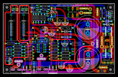
The only thing that they share is the output relay, as I think was done on the first Penasa version. The rest is completely separate for both channels.
PCB size is 150mm x 95mm.
The only thing that they share is the output relay, as I think was done on the first Penasa version. The rest is completely separate for both channels.
PCB size is 150mm x 95mm.
hi siva,
remember me,i tought of just check out your miniref design. siva when you have designed the current pump you have changed the gain of the pump to 2 but mauro designed the current pump to have unity gain so that higher bridge outpu impedance of 500ohm was attainable right?have you checked on that?
then why have you used those 22nf cap in parrel with 220uf ....i know 220uf is for unity DC gain
should that cap come in parrel to 12k res
when you have designed the current pump you have changed the gain of the pump to 2 but mauro designed the current pump to have unity gain so that higher bridge outpu impedance of 500ohm was attainable right?have you checked on that?
then why have you used those 22nf cap in parrel with 220uf ....i know 220uf is for unity DC gain
should that cap come in parrel to 12k res
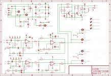
Hi Vishnu: note that the Miniref is not the same topology as the MyRef, although many ideas have been borrowed from it. The Miniref is actually a nested Jung-topology amp, with both the inner opamp and the GNFB loops being non-inverting voltage-series feedback loops. The Howland current-pump (LM1875) is also non-inverting. The transconductance (I/V gain) of the Howland pump (as shown) is the same as that of the MyRef - this has been done to allow the use of existing MyRef parts without change.
I'm not sure about what you mean by bridge output impedance, but if you mean the output impedance of the Howland current pump, it's pretty high (comparable to the MyRef) and depends largely on the matching of the Howland resistor network (which can be matched to the same accuracy as that of the MyRef).
The 22nF cap is just a HF bypass for the 220uF DC blocking cap. Depending on the quality of the DC blocking cap, its use is optional. If the DC blocking cap is a Black Gate, Elna Cerafine, Panasonic Pureism or Nichicon KZ, you can probably omit the 22nF bypass. For a Panasonic FM, Elna Silmic/RJH/RJJ or similar, you may want to use the 22nF bypass - it's a matter of personal taste.
The 12k gain-setting resistance doesn't need a cap in parallel with it - the compensation schema for a Jung-topology amp is very different from the MyRef, and is provided by a single modified-Deboo integrator, which is the 22pF + 1k network in this schematic. In simulation, it has a fairly comfortable phase-margin of 80 degrees or so, which can be increased further if needed.
Note that a double-sided PCB with careful layout is mandatory if you want decent sonics. The topology is fairly forgiving with respect to stability, but the parasitics from a point-to-point build can lead to unpredictable sonics.
siva in national datasheet it is specified that the bride output current is given by
(Rf/Ri)*Vin/Rsense,substituting the values of design we get unity gain....soory there i was first refering your first schematic version,
in the datasheet they have also told of the bridge output impedance to be some R/deltaR
i couldnt get it really...please explain if you got it correctly.
Then the 1k+22pf combination ,is it for preventing oscillation at high frequencis?is it possible to raise the cap value to .001uF range and compencate in resistor value because its difficult to get good quality pf values for me
Count me in for a group buy if this ever gets tested and what-not.
I would be interested as well. Please let me know if you ever decide to progress with this one.
+1Count me in for a group buy if this ever gets tested and what-not.
OK, there seems to be some interest, but I don't have the time to order the PCBs and offer a Group Buy. Therefore, I'm posting the Eagle schematics and layout of MiniRef 1.02 here, under the terms of the GNU GPL. They're free to use and modify as long as the original credits are retained on all derivative works. No warranty, express or implied, is offered.
Attachments
- Home
- Amplifiers
- Chip Amps
- MiniRef Schematic and PCB layout