My apologies for the vague answer, but... For 2.4 GHz WiFi the wavelength is almost 12.5 cm, so I guess you would need a hole that is large compared to 12.5 cm if you want the degradation of the WiFi reception to be very small. If your Pi is right next to a wireless router, you can probably get away with a much smaller gap or hole, because you can then allow considerable attenuation of the RF signal without losing connectivity.
My apologies for the vague answer, but... For 2.4 GHz WiFi the wavelength is almost 12.5 cm, so I guess you would need a hole that is large compared to 12.5 cm if you want the degradation of the WiFi reception to be very small. If your Pi is right next to a wireless router, you can probably get away with a much smaller gap or hole, because you can then allow considerable attenuation of the RF signal without losing connectivity.
Thank you for the feedback. Its much appreciated.
The cutoff condition for an aperture is λ > perimeter: it then functions as attenuator.
However, respecting perimeter > λ does not guarantee a good transmission, it depends on a lot of other factors.
Note that the aperture can take many forms and shapes: it can be a simple slit, straight or sinuating, it could be an isolated panel or part of a panel, etc
However, respecting perimeter > λ does not guarantee a good transmission, it depends on a lot of other factors.
Note that the aperture can take many forms and shapes: it can be a simple slit, straight or sinuating, it could be an isolated panel or part of a panel, etc
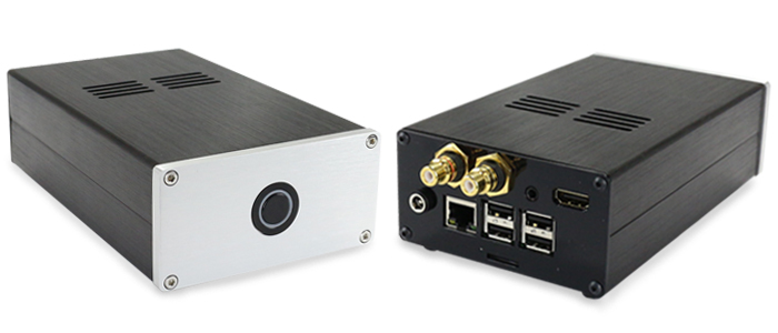
slots can be tiny width and they will leak some RF.
That example case has lot's of different slots.
The ventilation slots are wide.
The slots where the face plate and back plate attach to the case.
The slots where the upper and lower halves fit together.
For a slot to not pass RF there must be an electrical connection ACROSS the slot.
anodising and paint are not an electrical connection.
What about placing 4 washers between the backplate and the case?
Adjust the thickness of these washers to adjust the gap in the slots. Worth experimenting.
1mm might be enough. Would 3mm be too ugly?
slots can be tiny width and they will leak some RF.
That example case has lot's of different slots.
The ventilation slots are wide.
The slots where the face plate and back plate attach to the case.
The slots where the upper and lower halves fit together.
For a slot to not pass RF there must be an electrical connection ACROSS the slot.
anodising and paint are not an electrical connection.
What about placing 4 washers between the backplate and the case?
Adjust the thickness of these washers to adjust the gap in the slots. Worth experimenting.
1mm might be enough. Would 3mm be too ugly?
The washer idea is brilliant. Thanks for that and the insight into RF blocking.
This (the washers) as a first step could circumvent the cutting and drilling.

1mm - 3mm is definately acceptable.
An external antenna is the only way IMHO.
This would the last resort.
- Status
- This old topic is closed. If you want to reopen this topic, contact a moderator using the "Report Post" button.
- Home
- Design & Build
- Construction Tips
- Minimum Gap (in aluminium) for Wifi transmission ?