That's five. Maybe six.
But seriously, I would have thought EQing an H-Frame sub is one of the easier DIY dipole tasks, especially compared to EQing the midrange which is still bugging me after ten years.
If the H-frame is the same width and depth as the Orions, with the same driver, it should require the same EQ.
I don't find eqing the mids any more difficult that the woofer. I have outlined one approach I have used sucessfully in the ABC Dipole design guide. Perhaps it is because I know what midrange response I want to target?
The OP asked about eqing the woofer to a 35 Hz cut off. That is not the orion alignment.
Last edited:
Perhaps I should have been more specific and said 'EQing the mids in an Orion/Phoenix style speaker with the W22' where you have interaction of the dipole EQ, the dipole peak EQ, the driver resonance EQ, and the crossover is a bitch.
One of the nifty things about using a digital crossover is that I have files for all of the different settings I've tried over the ten years or so I have had my speakers. My current settings are pretty close to the latest Orion ASP (based on comparing my files with other digital rebels and doing some listening and measuring tests with an ASP). And I was given semi-approved files for the original Orion back in 2003.
Flicking between them it is hard to believe they are the same speaker, even though both have that dipole magic. At least I didn't have to resolder the boards each time.
The current iteration does sound better, but I'm getting tired of being able to play God with my speakers. I just want them to be right. And when, as mentioned, five different people who are smarter than me have five different suggestions for the simple act of EQing an H-frame I find it a tad depressing.
That's why I have been trying out turnkey no-tweak commercial speakers against mine recently. Alas, none have sounded as good but I have high hopes for the Apogees heading towards me now.
Mind you I had the same high hopes for the Maggies which preceded them.
Unfortunately the only thing that has sounded better than my digiOrions is the test speaker I whipped up for a narrow baffle 4 way like the LX521/Note.
I really don't want a 4 way.
Perhaps I should have been more specific and said 'EQing the mids in an Orion/Phoenix style speaker with the W22' where you have interaction of the dipole EQ, the dipole peak EQ, the driver resonance EQ, and the crossover is a bitch.
One of the nifty things about using a digital crossover is that I have files for all of the different settings I've tried over the ten years or so I have had my speakers. My current settings are pretty close to the latest Orion ASP (based on comparing my files with other digital rebels and doing some listening and measuring tests with an ASP). And I was given semi-approved files for the original Orion back in 2003.
That is why I developed midrange design feature of the ABC Dipole spread sheet. Here is a screen shot:
An externally hosted image should be here but it was not working when we last tested it.
The spread sheet helps design the high pass, the dipole eq and the dipole peak notch filters. I target an LR4 acoustic HP filter and the circuit uses a Q=1, 2nd order HP, a low pass shelf for dipole EQ and the notch to reduce the dipole peak. I did not do the LP filter because at the time I was doing passive mid/tweeter and used SoundEasy to design the LP mid filter. But as you can see, it would be pretty easy to address the breakup peak at 3.2K and add an LP filter.
I took the results from ABC Dipole, set them up in SoundEasy, added a B3 LP filter and a notch filter for the breakup and let SoundEasy optimize for the LP cut off frequency and the notch Fc,Q and dB cut to match the LR4 acoustic LP target:
An externally hosted image should be here but it was not working when we last tested it.
The above took me about 10 minutes. From there it pretty easy to convert the Q notch filters to the miniDSP parameters and load it up. No having to decide on what caps, resistors and opamps to use. No circuit layout. If a passive LP, no wondering if the topology is the best. Then tweak to hearts content, and as you note save the config files so you can compare. I particularly like the ability to load 4 config files in the 2x8 and switch on the fly. I'm not interested in designing an analog ASP which will be obsolete if I change speakers. I just this morning sold another set of Note II RS plans to a previous Orion/Pluto owner who was considering the LX521 but decided on the Note II because he didn't want to build another analog ASP.
I am all up for trying out recomendations from people, at least I can see how the measure and sound.
So just to clear a few things up, do you measure an h-frame at the opening or close to the dust cap to work out the driver EQ? And then at 1metre distance to work out the dipole roll off? Can an LT filter not be used as a Q boost and driver EQ in one?
The high pass filter to limit cone excursion makes sense to me espesially as I am using only one woofer per speaker.
I am all up for trying out recomendations from people, at least I can see how the measure and sound.
So just to clear a few things up, do you measure an h-frame at the opening or close to the dust cap to work out the driver EQ? And then at 1metre distance to work out the dipole roll off? Can an LT filter not be used as a Q boost and driver EQ in one?
The high pass filter to limit cone excursion makes sense to me espesially as I am using only one woofer per speaker.
My approach to designing a dipole woofer is to measure the SPL in the plane of the opening. Measure both the front and rear. The add delay to the rear response. The delay should be H frame length in feet divided by 1128. 1128 is the speed of sound in feet per second. Then sum the front and delayed rear response. This will be a very good approximation to the far field dipole axial response without equalization applied. A one meter measurement will not be representative of the free field response because the dipole behavior only exists in the far field and takes some distance to develope.
If you use the Q boost, Q notch approach to equalize the woofer response you will not need to HP filter the woofer as the acoustic response will be a 4th order high pass alignment and the woofer excursion will decrease below the woofer cut off. If you want additional protection you could add an electrical B2 high pass stage in the eq at say 20 Hz.
The LT can only shift the poles so the woofer would still require dipole EQ. Additionally, due to the TS parameted os the XLS woofers I don't think an LT is suitable. The newer woofer seem to have different TS parameters so this may not be the case.
Well, I just used the ABC Dipole design spreadsheet, the instructions are very clear and well written.
I hope the filters are easily implemented in Minidsp but this is what I cam up with.
I set FC at 35hz in the spreadsheet and also applied an LR4 HPF at FC to limit cone excursion.
I just need to measure the H-frame and see how it looks.
I hope the filters are easily implemented in Minidsp but this is what I cam up with.
I set FC at 35hz in the spreadsheet and also applied an LR4 HPF at FC to limit cone excursion.
I just need to measure the H-frame and see how it looks.
An externally hosted image should be here but it was not working when we last tested it.
Last edited:
You're doing great Rich!
And thanks for the help John!
I had a great time with just a 2x4 and my old open baffles!
(FE83, RS1197, PR170MO + APT80, Beta12LT + RS pod tweet and then Wayne's 1 Pi, 2 Pi (sort of) and 3 Pi front baffle)

http://www.diyaudio.com/forums/mult...-tool-real-time-dsp-crossover-adjustment.html
I'll be getting another 2x4 soon so I'll be joining you guys with active 3-way (1 or 2x Beta15, PR170MO, super tweet ...)
or maybe B15, Beta12LT, super tweet ... You know how it is!
I'm taking notes!
Cheers,
Jeff
And thanks for the help John!
I had a great time with just a 2x4 and my old open baffles!
(FE83, RS1197, PR170MO + APT80, Beta12LT + RS pod tweet and then Wayne's 1 Pi, 2 Pi (sort of) and 3 Pi front baffle)
http://www.diyaudio.com/forums/mult...-tool-real-time-dsp-crossover-adjustment.html
I'll be getting another 2x4 soon so I'll be joining you guys with active 3-way (1 or 2x Beta15, PR170MO, super tweet ...)
or maybe B15, Beta12LT, super tweet ...
You know how it is! I'm taking notes!
Cheers,
Jeff
Last edited:
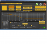
There is a problem implementing the Q notch filter with the miniDSP because miniDSP uses a different definition of Q for the peak/notch filters. But you should not need a notch for this H frame. For the shelf filters in miniDSP use Q = 1. The dipole EQrequires 24dB gain, but miniDSP will not allow a single filter to have a gain more that 16 dB. Thus you must use two shelfs. One with center frequency 70 Hz and one with a center frequency of 285 Hz. Ideally they should both have a gain of 12dB so the total gain is 24 dB. The miniDSP might not be happy with that at higher volume levels (assuming you are using analog input). Note that the dipole =monopole frequency (Fequal) is at 191 Hz and the gain of the dipole EQ at 191 is 9.9 dB (10dB). Thus instead of making both shelves 12dB gain Low shelves, make the 285 Hz shelf a High shelf with gain of -12dB. NOTE -12! This will yield a response that is down 2dB relative to Fequal. To correct that you can add a 4th stage of EQ using the biquad option. For 2 dB gain set B0 = 1.26. All this yields a 35 Hz Q = 0.5 high pass response for the woofer with nominal sensitivity the same as if the woofer were a monopole (sealed box). That should be low passed to your midrange at no higher than about 300 Hz. I would suggest 150 Hz as a better limit. You may also wish to add a high pass filter to protect the woofer from over excursion. I would suggest a 15 Hz B2.
So the eq, including the 15 Hz B2 high pass would look like this:
In summary the EQ is
Stage 1: 58 Hz, +8.8dB, Q = 1, Low shelf,
Stage 2: 70 Hz, +12dB, Q=1, Low shelf,
Stage 3: 285 Hz, -12dB, Q=1, High shelf
Stage 4: Biquad, B0 = 1.26. (+2dB gain)
Stage 5: Biquad, 15 Hz, 2nd order Butterworth high pass (use the Biquad Calculator).
If the woofers are too low in level I would recommend attenuation the other channels rather that adding gain to the woofer. However, to ad gain to the woofer you just increase B0 in stage 4. B0 = 10^(gain in dB/20).
That is how I would impliment the ABC Dipole calculated EQ in the miniDSP.
So the eq, including the 15 Hz B2 high pass would look like this:
An externally hosted image should be here but it was not working when we last tested it.
In summary the EQ is
Stage 1: 58 Hz, +8.8dB, Q = 1, Low shelf,
Stage 2: 70 Hz, +12dB, Q=1, Low shelf,
Stage 3: 285 Hz, -12dB, Q=1, High shelf
Stage 4: Biquad, B0 = 1.26. (+2dB gain)
Stage 5: Biquad, 15 Hz, 2nd order Butterworth high pass (use the Biquad Calculator).
If the woofers are too low in level I would recommend attenuation the other channels rather that adding gain to the woofer. However, to ad gain to the woofer you just increase B0 in stage 4. B0 = 10^(gain in dB/20).
That is how I would impliment the ABC Dipole calculated EQ in the miniDSP.
I had used an LR4 at the FC as that was recommended in the ABC dipole design, I shall give your suggestion a go in using a B2 at 15Hz.
I understand that Minidsp has it's limitations regarding max gain, that's why I used a combination of both a high shelf and low shelf filter using the same center frequency 142Hz for each with 12dB and -12dB gain. What I don't understand is how you came up with two different center frequencies?
I hope I am on the right track, and thank you for taking the time to explain it to me.
Is it SQRT of FH x center shelf frequency and FC x center shelf frequency, so... (SQRT 575 x 142=285) and (SQRT 35 x 142=70)
Last edited:
The LR4 recommended by ABC is for the low pass filter between the woofer and mid. ABC does not address the high pass I have recommended for limiting excursion. I have placed it at 15 Hz so that the initial woofer roll off will still follow a 2nd order, Q = 0.5 high pass response around the 35 Hz cut off. If you want to have greater protection you could use a higher order filter.
The thing about the shelves is that they have one pole and one zero at frequencies Fp and F0. The center frequency is the sqrt(Fp x F0) and gain = 20 log((F0/Fp)). So the dipole EQ has pole at 35 and zero at 575 HZ. This can be divided into two shelves by placing a pole and zero anywhere between 35 and 575 Hz. If placed at 142 Hz then both shelves with have the same gain, 12dB. One shelf has Fp = 35, F0 = 142. The other has Fp = 142, F0 = 575. When combined the pole and zero at 142 Hz cancel and you have the original response. You already understand the trick of replacing one low shelf with a high shelf to limit the total gain while retaining the correct shape of the EQ.
Hope this helps. Have fun with your woofer experiment.
John/Rich,
To create a standard, first-order shelving filter (with gain greater than 16db) you would indeed use two filters, but the settings should be at the same frequency. If you separate the filter center frequencies (and leave the Q setting at 1) you no longer have a textbook 6db/octave shelving filter.
With some of the digital boxes (like the DCX2496) you are required to separate the programmed frequency of each filter to create the proper cascaded filter function, but not so the miniDSP since it uses "center" frequencies for the shelving settings.
Anyways, your example of 35Hz-757Hz yields a gain of 24db at center of 142hz. So, to program into a miniDSP you have three options. (All three have exactly the same curve, just offset in gain for utilizing different gain structure.)
F = 142Hz, Gain = 12, Q = 1, Low-shelf,
F = 142Hz, Gain = 12, Q = 1, Low-shelf,
Or
F = 142Hz, Gain = 12, Q = 1, Low-shelf,
F = 142Hz, Gain = -12, Q = 1, High-shelf,
Or
F = 142Hz, Gain = -12, Q = 1, High-shelf,
F = 142Hz, Gain = -12, Q = 1, High-shelf,
Attached is a photo of the middle example:
Cheers,
Dave.
Attachments
Last edited:
John/Rich,
To create a standard, first-order shelving filter (with gain greater than 16db) you would indeed use two filters, but the settings should be at the same frequency. If you separate the filter center frequencies (and leave the Q setting at 1) you no longer have a textbook 6db/octave shelving filter.
With some of the digital boxes (like the DCX2496) you are required to separate the programmed frequency of each filter to create the proper cascaded filter function, but not so the miniDSP since it uses "center" frequencies for the shelving settings.
Anyways, your example of 35Hz-757Hz yields a gain of 24db at center of 142hz. So, to program into a miniDSP you have three options. (All three have exactly the same curve, just offset in gain for utilizing different gain structure.)
F = 142Hz, Gain = 12, Q = 1, Low-shelf,
F = 142Hz, Gain = 12, Q = 1, Low-shelf,
Or
F = 142Hz, Gain = 12, Q = 1, Low-shelf,
F = 142Hz, Gain = -12, Q = 1, High-shelf,
Or
F = 142Hz, Gain = -12, Q = 1, High-shelf,
F = 142Hz, Gain = -12, Q = 1, High-shelf,
Attached is a photo of the middle example:
Cheers,
Dave.
That is incorrect, Dave. This figure compares a 1st order shelf with Fc = 142, +24dB with two shelves cascaded, each with Fc = 142, +12dB.
An externally hosted image should be here but it was not working when we last tested it.
The difference is clear. A 1st order shelf has one pole and one zero in the transfer function. Cascading two identical shelved with 1/2 the gain and the same Fc yields a transfer function with two poles and two zeros. What I posted previously is correct.
When the center frequencies are staggered as I specified, at 70 and 285Hz the result is as below, perfect match.
An externally hosted image should be here but it was not working when we last tested it.
The gain of a 1st order shelf is F0/Fp= 575/35 = 16..42 > 24dB.
What you have is a 2nd order shelf with gain = (Fo/Fp)^2 = (285/70)^2 = 16.57 > 24dB. (ignoring round off errors)
Last edited:
Yep, sorry I forgot about the known "Q-issue" with the miniDSP.
You do need to alter the Q setting (on some) of the miniDSP plug-ins to achieve the textbook first-order shelf if using filters with the same frequencies.
So, for this 35-575 example set both filters to 142Hz, and 12db, and change Q from 1 to 0.8. It looks good then.
MiniDSP has adjusted/corrected the Q "problem" with some of the other/newer plug-ins, so a person needs to be aware of which plugin (and kit) is being used and check accordingly. Sorry for the possible confusion.
Cheers,
Dave.
You do need to alter the Q setting (on some) of the miniDSP plug-ins to achieve the textbook first-order shelf if using filters with the same frequencies.
So, for this 35-575 example set both filters to 142Hz, and 12db, and change Q from 1 to 0.8. It looks good then.
MiniDSP has adjusted/corrected the Q "problem" with some of the other/newer plug-ins, so a person needs to be aware of which plugin (and kit) is being used and check accordingly.
Sorry for the possible confusion.Cheers,
Dave.
Last edited:
Or use the available spread sheet and enter the coefficients in advanced mode ?MiniDSP has adjusted/corrected the Q "problem" with some of the other/newer plug-ins, so a person needs to be aware of which plugin is being used and check accordingly.
Yep, that will work too. IMHO, it's preferable to keep the miniDSP programming in the "basic" mode if possible.....especially for those that are new to the platform.
It doesn't help that the default Q setting for miniDSP shelving filters is "0.5".....which doesn't correspond to a first-order shelving filter if you were to program it without changing that parameter.
There are many idiosyncrasies of the miniDSP operation a user needs to be aware of. John K. himself noticed a Q problem with the notch filtering settings a year or two ago.
Cheers,
Dave.
IMHO, it's preferable to keep the miniDSP programming in the "basic" mode if possible.....especially for those that are new to the platform.It doesn't help that the default Q setting for miniDSP shelving filters is "0.5".....which doesn't correspond to a first-order shelving filter if you were to program it without changing that parameter.
There are many idiosyncrasies of the miniDSP operation a user needs to be aware of. John K. himself noticed a Q problem with the notch filtering settings a year or two ago.
Cheers,
Dave.
Yep, sorry I forgot about the known "Q-issue" with the miniDSP.
You do need to alter the Q setting (on some) of the miniDSP plug-ins to achieve the textbook first-order shelf if using filters with the same frequencies.
So, for this 35-575 example set both filters to 142Hz, and 12db, and change Q from 1 to 0.8. It looks good then.
MiniDSP has adjusted/corrected the Q "problem" with some of the other/newer plug-ins, so a person needs to be aware of which plugin (and kit) is being used and check accordingly.
Cheers,
Dave.
It is not a Q issue. It is not possible to cascade two 1st order shelves with the same gain and center frequency and have the same response as a single 1st order shelf. There cascaded pair will have two zeros and two poles. The net transfer function will be 2nd order have s^2 in both the numerator and denominator where as the 1st order shelf only has s^1.
It doesn't help that the default Q setting for miniDSP shelving filters is "0.5".....which doesn't correspond to a first-order shelving filter if you were to program it without changing that parameter.
Cheers,
Dave.
This also depends on what version you have. I have a version of the 2way advance and the 4way advanced that require Q = 1 for a "correct" 1st order shelf. I have a newer version of the 2way advanced that requires Q = 0.5. And my 2x8 plug-in requires Q = 0.5.
For this reason, and the Q peak/notch this, I always input biquad coefficients for any EQ and then check by measuring the results and comparing them to known behavior.
I guess if I had one complaint about miniDSP it would be their deviation form the standard analog definitions of Q. Point in fact, a true, analog, 1st order shelf doesn't have a Q.
- Status
- This old topic is closed. If you want to reopen this topic, contact a moderator using the "Report Post" button.
- Home
- Loudspeakers
- Multi-Way
- MiniDSP H-Frame.