Member
Joined 2009
Paid Member
D
Deleted member 148505
looking good - be careful you don't end up like me, with 5 amps not quite finished !
After a year.. finished soldering all the components.. Now I have 4 amps not yet finished
 , Hopefully i'll finish this on July 2016
Attachments
D
Deleted member 148505
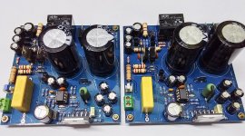
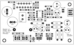
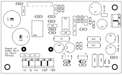
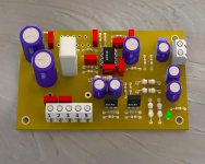
Finally wired up after a year in my cabinet. Got no problems encountered, initial power up is good.
Sound is good, which inspired me to create a module without built in power supply, for connecting with SMPS etc..
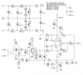
Supply for LM318 is RC + shunt, can be connected to external supply through optional header.

Sound is good, which inspired me to create a module without built in power supply, for connecting with SMPS etc..
Supply for LM318 is RC + shunt, can be connected to external supply through optional header.
Attachments
D
Deleted member 148505
Are you going to sell these on eBay?
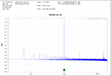
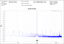
Will test thd first, size is 5" x 2.1"
main section is only 2" x 1.2"
pcb design not yet finalized
Attachments
D
Deleted member 148505
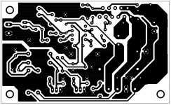
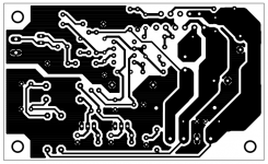
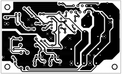
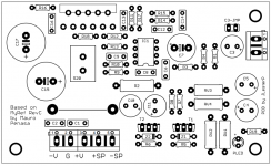
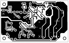
Free layout update
Size 3.8 x 2.3 inches
only 1 jumper
feel free to suggest improvements on pcb design
Size 3.8 x 2.3 inches
only 1 jumper
feel free to suggest improvements on pcb design
Attachments

D
Deleted member 148505
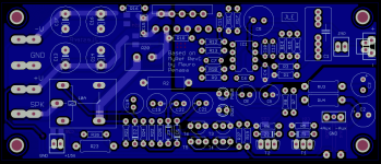
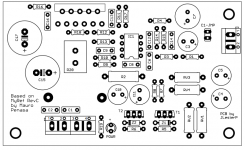
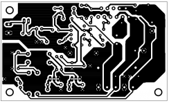
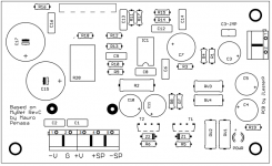
Slight update on pcb tracks
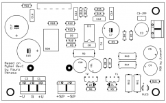
all poly caps = 5mm lead spacing
c3, c4, c5, c10, c11 = 8mm diameter
c7 - 10.5mm diameter
c15, c17 = 13mm diameter
jumper 2.5mm lead spacing
input terminal 5mm lead spacing
R20 = 7W TWM or SQM vertical resistor, or TO-220 2pin resistor
all poly caps = 5mm lead spacing
c3, c4, c5, c10, c11 = 8mm diameter
c7 - 10.5mm diameter
c15, c17 = 13mm diameter
jumper 2.5mm lead spacing
input terminal 5mm lead spacing
R20 = 7W TWM or SQM vertical resistor, or TO-220 2pin resistor
Attachments
D
Deleted member 148505
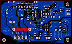
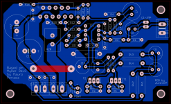
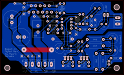
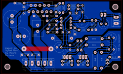
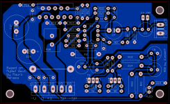
Try to connect R1, R2 and R4 closer together. Shorten the traces R2 and R14 to the speaker outputs. Speaker return is missing. Keep the loops as small as possible.
Thank you for your suggestion, the board is limited only to 1 layer and 3.8 x 2.3 inches so there will be compromises.
In my previous layout, speaker return is intended to be connected to the power supply star ground and +speaker should be connected to external speaker protect module.
Here is the updated layout.
Attachments
D
Deleted member 148505
See if this helps:
Rotate and move up/left C12, R14 and R15 so that they are next to R17. This should give you some room to move C7 down/left.
Making a PCB layout is the most frustrating thing ever. I am never really happy with what I design.
Yep balancing benefits and trade-offs
How about this.
Attachments
D
Deleted member 148505
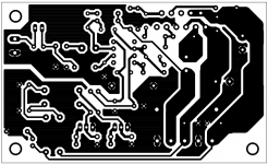
no more suggestions, i guess it's nearly perfect.
uploading final layout.
uploading final layout.
Attachments

D
Deleted member 148505
D
Deleted member 148505
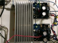
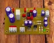
This one needs DC supply since it doesn't have onboard rectifiers.
Attached update.
Attached update.
Attachments
Last edited by a moderator:
D
Deleted member 148505
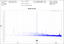
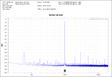
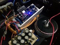
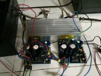
My Ref on toroidal +/-35V DC supply.
This amplifier is not the same as in #76
D
Deleted member 148505
This amplifier is not the same as in #76
Yes, that's my commercial version which is double sided and includes speaker protection circuit.
- Status
- This old topic is closed. If you want to reopen this topic, contact a moderator using the "Report Post" button.
- Home
- Amplifiers
- Chip Amps
- Mini My Ref Rev C