Hi everyone,
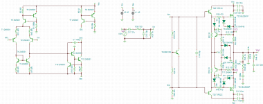
I'm projecting a MOSFET output power amplifier based on a design I've seen in Bob Cordell's book "Designing Audio Power Amplifiers", but I've a problem, it seems that the quiescent current passing thru the MOSFET output devices are shifting the phase of the closed loop to dangerous levels, so I'd to increase the value of the Miller Compensation Capacitor to high levels, but this leads to another problem, because the slew rate it's reduced. In simulations I've made in TINA something strange are happening because when I have a closed loop gain of about 5-10 V/V the harmonic distortion in the FFT for 20 kHZ is below 0.5 %, for higher gain levels are enormous, higher than 1% !!!
I don't know if this is a common problem in MOSFET amplifiers or Bob Cordell's designs, but I've tried with other designs and the result is similar, could be a problem with TINA? If so, how can I fix that? It's better to use another simulator?
PS: The VI limiter circuit, and the clamping diodes aren't causing any strange effect, without it the result is the same.
Thank you very much for your attention
Best regards,
Daniel Almeida
Attachments
Last edited:
The only strange I can see is R49 47k from Snk to ground.
But this should not be a problem.
Not such problem as you tell about.
For higher gain the THD should be higher.
But more than 1% is not okay.
Do you think you have good models for all your transistors?
You have tried to use other MOSFET?
But this should not be a problem.
Not such problem as you tell about.
For higher gain the THD should be higher.
But more than 1% is not okay.
Do you think you have good models for all your transistors?
You have tried to use other MOSFET?
I've tried with the pair of IRFPs and the result it's even worse, I've to use a 220 pF capacitor and even with low voltage gains (10 V/V) the harmonic distortion is higher than 1%.
This effect of phase shift due to quiescent current passing thru the output devices is common?
Because of that I've to increase te Miller capacitor, decreasing the slew rate, another way that works without reducing the slew rate so much consists in trying to put random resisistor values in series with the Miller compensation capacitor to add a zero until phase margin of at least 45º is reached, but this is a strange procedure and I don't know if it works in real life, I've never ever seen a working desin of audio power amplifier with zer-pole compensation.
Please can you help me here, does anyone have tried to do a similar project?
Best regards,
Daniel Almeida
Last edited:
There's something odd here. 100pF should be big enough. With 470 Ohm emitter resistors in the input stage and a gain of 10, the unity loop gain frequency is only about 300KHz.
Are you sure the output devices are biased properly? You could check the quiescent voltage across the 0.33 Ohm emitter resistors.
I don't understand what you mean by "phase shift due to quiescent current passing thru the output devices". Quiescent current doesn't cause phase shift. Lack of quiescent current may cause problems though.
Last edited:
Possibly. Depends if the MOSFET models are any good.
There are some decent SPICE models on Bob Cordell's website here: CordellAudio.com - Home
There are some decent SPICE models on Bob Cordell's website here: CordellAudio.com - Home
")
Thank you very much for replying,
but I've tried to do that and the result is the same
Best regards,
Daniel Almeida
Daniel
It really would be helpful to see the loop gain. Just put an ac source inline with the nfl node and plot the one end divided by the other.
edit: It appears that C2 is in the gain node although bootstrapped to the output (but there is significant loss to the output node).
Thanks
-Antonio
Last edited:
Dont understand why removing C2 doesn't help but you really need to perform a loop gain measurement.
Just one ac source between the output nfl node and the input to the feedback divider network (input ac source set to zero). Then ac analysis and plot vac+/vac- to get a good estimate of the loop gain.
Thanks
-Antonio
Just one ac source between the output nfl node and the input to the feedback divider network (input ac source set to zero). Then ac analysis and plot vac+/vac- to get a good estimate of the loop gain.
Thanks
-Antonio
Hi everyone and thank you very much for your help,
The problem could be caused by poor modeling in TINA.
I'm now using LTSpice with Bob Cordell's models and the models I've got in this forum for the output pair. And the difference is huge, THD1<0.03%, THD20<0.5%, for a 28 V/V voltage gain. The amplifier with 150pF Miller capacitor is stable for all gains between 1 and 100 V/V, for gains lower than 2, the amplifier shows signs of overshooting at high frequencies, but I Don't need to use the amplifier as voltage buffer.
PS: I didn't tried the vi limiter yet, so I don't know if the bootstrapping effect could be noticed, but you're right magnoman, a capacitor between the vas current source and the output could bootstrap in this case at high frequencies, old STKs from Sanyo and some other actual chipamps from ST use this vas topology, because only one uF capacitor and two resistors are needed to put the amplifier working, no constant current source needed on VAS.
Best regards,
Daniel Almeida
Last edited:
- Status
- This old topic is closed. If you want to reopen this topic, contact a moderator using the "Report Post" button.
- Home
- Amplifiers
- Solid State
- Miller Compensation Capacitor vs Slew Rate