Hi David,
Thank you for all your help with my project. Learning a lot.")
Wonder if you could help me with another question?
Have managed to transfer the nested probe to my schematic and adapted a little to include your common mode probe. Wondering whether it is possible to have three nested probes?
The reason is I think I have managed to get my head around my nested loops. I think it goes CMCL inside the VAS and the VAS is inside the Main loop. Think that to gain stability in the main loop the VAS has to be faster and for the VAS to be faster the CMCL needs to be faster. And as loops get faster stability margins reduce.
It would make life a lot easier to have 3 probes.
Thank you for giving your time.
Paul
PS. This is the project these questions relate to:
http://www.diyaudio.com/forums/solid-state/261304-cfa-amp-cmcl-hec-output-stage-2.html#post4080691
Thank you for all your help with my project. Learning a lot.
Wonder if you could help me with another question?
Have managed to transfer the nested probe to my schematic and adapted a little to include your common mode probe. Wondering whether it is possible to have three nested probes?
The reason is I think I have managed to get my head around my nested loops. I think it goes CMCL inside the VAS and the VAS is inside the Main loop. Think that to gain stability in the main loop the VAS has to be faster and for the VAS to be faster the CMCL needs to be faster. And as loops get faster stability margins reduce.
It would make life a lot easier to have 3 probes.
Thank you for giving your time.
Paul
PS. This is the project these questions relate to:
http://www.diyaudio.com/forums/solid-state/261304-cfa-amp-cmcl-hec-output-stage-2.html#post4080691
...Wonder if you could help me with another question?
...
my head around my nested loops. I think it goes CMCL inside the VAS and the VAS is inside the Main loop.
Sorry, this is not really correct.
The CMCL is not inside the VAS.
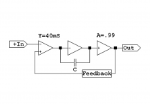
I usually find it easier to draw the amplifier as a block schematic like in the first picture below. This shows the VAS loop inside the main loop.
But I have yet to work out a neat way to show the CMCL, it would need a more detailed picture of the amplifier structure.
It is essentially an alternate mode, in parallel.
If you look at the earlier plot of my amp in post #24 http://www.diyaudio.com/forums/solid-state/261973-middlebrook-gft-probe-3.html#post4076143 you can see that the CMCL loop (labelled "Tian") behaves quite differently from the other loops and is slower. This is fine, it essentially establishes the DC conditions and does not need to be fast. So it can be very stable.
Think that to gain stability in the main loop the VAS has to be faster and for the VAS to be faster the CMCL needs to be faster...
It would make life a lot easier to have 3 probes...
There is a tricky interaction between the outer and inner loops.
Another manifestation of the "water-bed effect", try to push down to improve one area and it pushes up somewhere else inconvenient.
The two probes are useful to examine this but the third one is not usually needed. I included the CMCL loop plot for interest, but it usually does not require any attention once you have checked it is OK. Alterations to the main loops will have little effect on it.
So my 3 probe implementation is just ad-hoc, used for the earlier overview but not ready for distribution.
Best wishes
David
Attachments
Sorry, this is not really correct.
The CMCL is not inside the VAS.
I usually find it easier to draw the amplifier as a block schematic like in the first picture below. This shows the VAS loop inside the main loop.
But I have yet to work out a neat way to show the CMCL, it would need a more detailed picture of the amplifier structure.
It is essentially an alternate mode, in parallel.
If you look at the earlier plot of my amp in post #24 http://www.diyaudio.com/forums/solid-state/261973-middlebrook-gft-probe-3.html#post4076143 you can see that the CMCL loop (labelled "Tian") behaves quite differently from the other loops and is slower. This is fine, it essentially establishes the DC conditions and does not need to be fast. So it can be very stable.
Hi David,
Nothing to be sorry about.
I like to corrected when I'm wrong. It's the only way to learn. Can imagine a way to draw a block diagram of the amp. Could show the two VAS's and another block (CMCL) joining the two. By the way I like to imagine the amp as an onion.There is a tricky interaction between the outer and inner loops.
Another manifestation of the "water-bed effect", try to push down to improve one area and it pushes up somewhere else inconvenient.
The two probes are useful to examine this but the third one is not usually needed. I included the CMCL loop plot for interest, but it usually does not require any attention once you have checked it is OK. Alterations to the main loops will have little effect on it.
So my 3 probe implementation is just ad-hoc, used for the earlier overview but not ready for distribution.
Best wishes
David
Have seen this water-bed effect myself with the main loop and VAS loop. The reason for the interest in the 3rd probe for the CMCL is because the compensation for this loop is also part of the miller comp. So messing with the miller comp has an affect on the CMCL stability.
Can analyse the loop (I think) using blocking inductors / capacitors and an AC source but using a Tian probe is beyond my limited mind at present.
It's been enlightening using the two probes for the VAS and main loop. See things that you don't expect to happen.
Paul
P.S. Don't want to pollute your thread with specific examples eg. My current project. But the knowledge you have shared has been very useful...
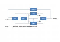
Here is my attempt at a simple man's block diagram of a symmetrical amp with CMCL where the compensation performs two functions.
Hopefully this is correct.
Yes, your situation is probably different to mine. I realized after I sent the previous post that I had done my own CMCL tests on an amp with Miller Input Compensation, where the two loops barely interact.
This lack of interaction was not why I chose MIC but is a nice bonus.
I would like to believe it's not just luck, I chose MIC specifically to minimise other interactions, like component tolerances.
I see it as similar to database normalisation, if you have come across that concept. If you have the structure correct then many consistency problems just can't happen.
In this case it is nice to be able to optimise each loop independently.
Best wishes
David
P.S. "Pollute my thread"
On the contrary, it's very educational to see how the ideas work on a different circuit, what is universal, what just incidental.The extra complexity of HEC in addition to all the other loops has really made me think.
Last edited:
Yes, your situation is probably different to mine. I realized after I sent the previous post that I had done my own CMCL tests on an amp with Miller Input Compensation, where the two loops barely interact.
This lack of interaction was not why I chose MIC but is a nice bonus.
I would like to believe it's not just luck, I chose MIC specifically to minimise other interactions, like component tolerances.
I see it as similar to database normalisation, if you have come across that concept. If you have the structure correct then many consistency problems just can't happen.
In this case it is nice to be able to optimise each loop independently.
Best wishes
David
P.S. "Pollute my thread"
The extra complexity of HEC in addition to all the other loops has really made me think.
Food for thought.... MIC... I did look at my circuit and thought it possibly lends itself to Cherry compensation too.
At some point I'll give the ideas in the maximum feedback paper you provided a link to a go.I like your idea of MIC and being able to tune the loops independently. Doubt your choice of MIC was "luck".
At the moment, for me the HEC is just an output stage block. Haven't given it too much thought. It's another part to optimise once the front end has been dealt with.
I think LTSpice is going to be working overtime this week.
Sometimes I feel out of my depth with this amplifier design but it is good to bounce ideas around with someone with much more knowledge.
Paul
PS you can also draw parallels with software design.
But I have yet to work out a neat way to show the CMCL, it would need a more detailed picture of the amplifier structure.
It is essentially an alternate mode, in parallel.
It is known as Common Mode Feedback Loop since the '60s. You'll find in this reference even the "CMCL" in Mr. Cordell HEC amplifier, as the "Simplest common-mode detector".
Can be simply analyzed using a common mode Tian probe that I posted elsewhere on this forum. As much as the Miller loops, that can be analyzed using a differential Tian probe.
...You'll find in this reference...
Can be simply analyzed using a common mode Tian probe that I posted elsewhere on this forum.
Hi Walter
Thanks for the reference.
Where did you post your common mode probe? Paul has a copy of my implementation and I am curious about yours.
Nice to have you in the thread because I appreciate your comments.
I noticed in post #24 that the outer loop gain (Tz1) is non-minimum phase, even at the low frequency of 10 kHz!
See that the phase drops even as the response peaks?
That doesn't affect the stability but made me think.
I have seen Spice show apparently implausible phase behaviour, Ian (Ihan) and others have noticed it, probably you too.
I assumed it was an arbitrary quirk but now suspect it is a manifestation of non minimum phase when there are multiple paths in a system.
You probably think this is my hobby-horse but I would like to have your input.
Have you seen these anomalous phase plots? Do you have an alternate explanation?
Best wishes
David
I noticed something similar. When I wasn't using HEC yet, the LG/Phase plots using the Tian probe corellated to (in)stability during regular simulation (squares, capacitive loads etc). If the probe would show "Unstable!" the schematic indeed was unstable. If the probe would show "Stable!" then the schematic is stable under various test conditions.
Hever, since I've included the HEC into the loop, I'm no longer sure I can trust the Tian probe results. When Tian says "Stable!" the circuit goes wonk and oscillates. When Tian says "Hmm that's wonky!" the circuit behaves properly.
What gives?
Hever, since I've included the HEC into the loop, I'm no longer sure I can trust the Tian probe results. When Tian says "Stable!" the circuit goes wonk and oscillates. When Tian says "Hmm that's wonky!" the circuit behaves properly.
What gives?
I noticed something similar. When I wasn't using HEC yet, the LG/Phase plots using the Tian probe corellated to (in)stability during regular simulation (squares, capacitive loads etc). If the probe would show "Unstable!" the schematic indeed was unstable. If the probe would show "Stable!" then the schematic is stable under various test conditions.
Hever, since I've included the HEC into the loop, I'm no longer sure I can trust the Tian probe results. When Tian says "Stable!" the circuit goes wonk and oscillates. When Tian says "Hmm that's wonky!" the circuit behaves properly.
What gives?
Have seen this with the HEC myself. Get something in LTspice that works then build it and it is only marginally stable (if that).
This is how I set up the HEC now and it works well albeit with higher THD. It always has rock solid stability in reality.
http://www.diyaudio.com/forums/solid-state/246700-random-amp-questions.html#post3795772
Post number 8.
Paul
...
since I've included the HEC into the loop
Have seen this with the HEC myself...
Once you have HEC then you have another loop to check and the behaviour is not very obvious. Hence my earlier comment that Paul's circuit had made me think.
As usual, you post just when it's bed time here
So, more tomorrow.
Best wishes
David
As usual, you post just when it's bed time here
Best wishes
David
Same for me here...
Have to post from work on the quiet when there is the small time overlap due to the time zones..Paul
Last edited:
OK, as promised after bedtime.
There is subtlety here that I still haven't completely clear in my own head.
Bode proved that if it is possible to find a wire where all the feedback can be disconnected with one cut, then the system can be analysed as if it had one loop.
For example if we have nested loops then we can cut the innermost loop and this will break all the outer ones.
So the correct point for an analysis may be inside a block if it contains a feedback loop of it's own.
But the alternate view, proved by Hurst, is that a block can be treated as a black box, and if it is stable then the addition of feedback around it won't lead to instability if the outside loop is stable.
These two views must be mathematically consistent, somehow the correct analysis inside the block must always work out so that the view from outside the block doesn't need to know about it.
Maybe it's just me but I don't find that completely obvious.
Now the tricky bit is that HEC doesn't have a point that cuts all feedback loops, once you have TMC and Paul's complicated compensation.
So you do have to look "inside" the HEC box.
And then, even so astute an analyst as JCX has noted that it's not obvious.
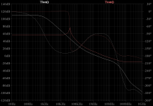
So here is Paul's amp, the loop gain outside the HEC loop is Tian(), the loop gain around the OPS once you have HEC is Tzan().
Note the cross-over frequency is 3 time more and the PM is decreased.
I think this is the explanation for some problems.
There are minor differences in the HEC included loop, dependent on where you check it, perhaps due to the difference between Tian and Middlebrook GFT assumptions.
I haven't even started to solve that discrepancy, and it's where I came in.
Best wishes
David
..At the moment, for me the HEC is just an output ... block. ... It's another part to optimise once the front end has been dealt with.
There is subtlety here that I still haven't completely clear in my own head.
Bode proved that if it is possible to find a wire where all the feedback can be disconnected with one cut, then the system can be analysed as if it had one loop.
For example if we have nested loops then we can cut the innermost loop and this will break all the outer ones.
So the correct point for an analysis may be inside a block if it contains a feedback loop of it's own.
But the alternate view, proved by Hurst, is that a block can be treated as a black box, and if it is stable then the addition of feedback around it won't lead to instability if the outside loop is stable.
These two views must be mathematically consistent, somehow the correct analysis inside the block must always work out so that the view from outside the block doesn't need to know about it.
Maybe it's just me but I don't find that completely obvious.
Now the tricky bit is that HEC doesn't have a point that cuts all feedback loops, once you have TMC and Paul's complicated compensation.
So you do have to look "inside" the HEC box.
And then, even so astute an analyst as JCX has noted that it's not obvious.
So here is Paul's amp, the loop gain outside the HEC loop is Tian(), the loop gain around the OPS once you have HEC is Tzan().
Note the cross-over frequency is 3 time more and the PM is decreased.
I think this is the explanation for some problems.
There are minor differences in the HEC included loop, dependent on where you check it, perhaps due to the difference between Tian and Middlebrook GFT assumptions.
I haven't even started to solve that discrepancy, and it's where I came in.
Best wishes
David
Attachments
Last edited:
OK, as promised after bedtime.
There is subtlety here that I still haven't completely clear in my own head.
Bode proved that if it is possible to find a wire where all the feedback can be disconnected with one cut, then the system can be analysed as if it had one loop.
For example if we have nested loops then we can cut the innermost loop and this will break all the outer ones.
So the correct point for an analysis may be inside a block if it contains a feedback loop of it's own.
But the alternate view, proved by Hurst, is that a block can be treated as a black box, and if it is stable then the addition of feedback around it won't lead to instability if the outside loop is stable.
These two views must be mathematically consistent, somehow the correct analysis inside the block must always work out so that the view from outside the block doesn't need to know about it.
Maybe it's just me but I don't find that completely obvious.
Now the tricky bit is that HEC doesn't have a point that cuts all feedback loops, once you have TMC and Paul's complicated compensation.
So you do have to look "inside" the HEC box.
And then, even so astute an analyst as JCX has noted that it's not obvious.
So here is Paul's amp, the loop gain outside the HEC loop is Tian(), the loop gain around the OPS once you have HEC is Tzan().
Note the cross-over frequency is 3 time more and the PM is decreased.
I think this is the explanation for some problems.
There are minor differences in the HEC included loop, dependent on where you check it, perhaps due to the difference between Tian and Middlebrook GFT assumptions.
I haven't even started to solve that discrepancy, and it's where I came in.
Best wishes
David
Thank you for this.
Now this is pushing my understanding...
Can understand the concepts of the first part of your reply. But you're right it's not completely obvious. Need to have more thinking time to try and get it clear in my head.
The analysis on my amp you have done is now beyond my understanding. However, can we say that TMC is not a good idea with HECs? Could moving to TPC be another option?
I can at least see that something is wrong with the Tzan loop gain plot. Peaks are always a warning sign. Now all I have to do understand your analysis.
Paul
Well it's taken about 3 hours to work out the probe placement for Tzan.
Don't ask me for any reasoning but a capacitor in series with R4 in my circuit of around 5nF removes the spike. You loose overall loopgain in the main loop though. Is it strictly stable? Not sure...
Paul
Don't ask me for any reasoning but a capacitor in series with R4 in my circuit of around 5nF removes the spike. You loose overall loopgain in the main loop though. Is it strictly stable? Not sure...
Paul
Last edited:
However, can we say that TMC is not a good idea with HECs?...
I said that HEC and TMC made your amp difficult to analyse, because I was sure about that.
But I didn't mean that this issue occurs only with HEC + TMC, I suspect this issue is common or inherent in HEC amplifiers, I just wasn't sure.
I qualified my statement because it seems extraordinary that such a basic issue could have been almost entirely overlooked.
JCX made a comment on it, as I noted, but I am unaware of any other.
I am not an expert on HEC so perhaps I just missed some work, does anyone have a prior reference?
Maybe it's been overlooked because people relied on the black box view, or because it does not fit the usual idealized feedback model?
It seems to be due to feed-forward in the HEC (feedback) network.
This is precisely why I asked about the Middlebrook GFT technique, because it covers this effect and helps to make it clear.
My initial reaction is almost shock, that it makes the usual HEC approach look suspect, perhaps misconceived.
I would like to be more certain before I start such a controversial debate.
Best wishes
David
Sorry it took that time to work it out.
I will post more details in future.
Last edited:
Sorry it took that time to work it out.
I will post more details in future.
No, it was a good thing in the end. A lot of concepts came together. Another zero added to the system (I think) may make it stable?
Then moved on to the HEC. It looks a strange beast at first but was able to see how to it worked on a very basic level.
Also, I don't think that TPC/TMC resistor thing suits my amplifier. Can see the mistakes made in the prototype that was difficult to get working. This time round the prototype worked first time. So at least there is something real to run basic stability tests on.
Loop analysis may finally be making sense
Paul
P.S. I could have asked the question... But the idea felt lazy.
Last edited:
I think the issue lies with 2 independant high-speed loops. When loops rival each other's speed while being autonomous, there may be events that 'disalign' their regulation, causing the loops to instantly fight and compensate each other. I have this issue when my HEC leaves clipping. I had this issue in the past when I was designing a powersupply with both a current and voltage control loop. Multiple 'solutions' giving the same answer so to speak.
- Status
- This old topic is closed. If you want to reopen this topic, contact a moderator using the "Report Post" button.
- Home
- Amplifiers
- Solid State
- Middlebrook "GFT" probe?