Thanks for the pic. I don't think for a moment the transformer is suspect.
Now I don't know how easy this thing is for you to work on and take measurements but, in the absence of any circuit diagrams it makes sense not to overlook anything. Remember though that these are basic tests only so don't get your hopes up too much.
OK we have to start somewhere. Please be careful measuring voltages... no danger, but a slip with the meter probes could cause damage. All the readings are taken with the black lead of the meter on chassis ground or "zero" volts point which can be the outer ground part of the RCA audio sockets. Some of these measurements may seem a bit random and even non related parts of the circuit but I'm working off the pics which is easier to describe from and trying to cover all supply possibilities.
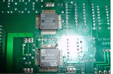
Pin markings on "normal" IC's begin with pin 1 at the spot or mark in the corner and work round the IC. So in the first one here pin 1 and 14 are opposite each other.
Looking at your picture in post #10 measure the voltage on pin 14 of the IC marked MC74HCD04N. It should be 5 volts.
To the left of that IC is a smaller one marked LF356N. Measure the voltages on pins 4 and 7. They should be equal and opposite. For example +9 volts on pin 7 and -9 volts on pin 4. The actual voltage could be anywhere from 5 to 18 volts depending on the design.
Thats a first step...
I'll post a bit more in a minute.
Now I don't know how easy this thing is for you to work on and take measurements but, in the absence of any circuit diagrams it makes sense not to overlook anything. Remember though that these are basic tests only so don't get your hopes up too much.
OK we have to start somewhere. Please be careful measuring voltages... no danger, but a slip with the meter probes could cause damage. All the readings are taken with the black lead of the meter on chassis ground or "zero" volts point which can be the outer ground part of the RCA audio sockets. Some of these measurements may seem a bit random and even non related parts of the circuit but I'm working off the pics which is easier to describe from and trying to cover all supply possibilities.
Pin markings on "normal" IC's begin with pin 1 at the spot or mark in the corner and work round the IC. So in the first one here pin 1 and 14 are opposite each other.
Looking at your picture in post #10 measure the voltage on pin 14 of the IC marked MC74HCD04N. It should be 5 volts.
To the left of that IC is a smaller one marked LF356N. Measure the voltages on pins 4 and 7. They should be equal and opposite. For example +9 volts on pin 7 and -9 volts on pin 4. The actual voltage could be anywhere from 5 to 18 volts depending on the design.
Thats a first step...
I'll post a bit more in a minute.
Try to find somebody in your neighbourhood (on this forum or similar) who is familiar with philips/marantz players. Would be easy for such a person to find the problem.
Checking the supplies is a good start and do-able, but after that you will soon need a scope to poke around.
I'm too far away myself
Checking the supplies is a good start and do-able, but after that you will soon need a scope to poke around.
I'm too far away myself
And on the TDA5709 (on the other board) the voltage on pins 6, 11 and 17.
What is on each ?
Also pins 4 and 8 of that little 8 legged IC the 4560. What is on those too.
It will probably be Friday before I can look in again in detail...
Measured the following:
MC7HCD04N Pin 14 4.69V
L356N Pin 4 15.09V
Pin 7 -14.93V
On Main Board
A -4.75V
B 0.00V
C -4.98V
D -4.97V
E -4.79V
F 0.00V
Also
TDA 5709
Pin 6 -4.58V
Pin 11 4.84V
Pin 12 -0.08V
4560
Pin 4 -13.87V
Pin 8 -9.7V
Some were a little tricky to measure but I would think are pretty accurate
David
They all sound good although the last one is a little unexpected and worth investigating... but again, don't get your hopes up, it may be normal.
The 4560 is a dual opamp and I suspect used for motor control. I would have expected pin 8 to be a positive reading. That said -9 on pin 8 and -15 on pin 4 is still a "valid" supply depending on the exact circuit application but it stands out a mile as not "normal".
I would recheck that reading and try and trace back pin 8 and see where it goes...
If anyone else is reading this do they know what other Philips models that "front end" board is used in ? It looks a standard Philips creation.
Those solid core wires used by Philips (they look like those anyway) can be fragile and fracture if they are bent around a lot so beware.
It will tomorrow before I can look again
My apologies but pin 4 on the 4560 measured at +13.87V and not -13.67V - I transcribed it to my pc incorrectly
I re-checked pin 8 and it is reading -9.7V
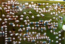
I have also attached a close up pic of the rear of the board - with the 8 pins of the 4560 top left on the rear view of the board - pin 8 is nearest the edge fourth from the right!
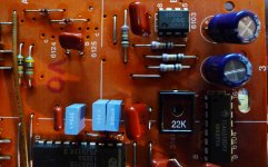
I attach also a pic of components in close proximity to the 4560
Once again thanks for your help
David
I re-checked pin 8 and it is reading -9.7V
I have also attached a close up pic of the rear of the board - with the 8 pins of the 4560 top left on the rear view of the board - pin 8 is nearest the edge fourth from the right!
I attach also a pic of components in close proximity to the 4560
Once again thanks for your help
David
Attachments
Hi David...
It seems the supplies as far as we can tell are OK. Without seeing a circuit diagram now I think realistically that's about as far as you can take it with only a multimeter for testing.
The CD spinning backwards could be a motor/drive/amplifier problem but without at least the correct circuit to give you very specific tests to perform, I fear it's beyond the scope of a thread such as this.
I've been looking at this unit for David and I've repaired the turntable motor fault. It is now responding correctly to the pulse-width modulated MC signal from the 'A' chip - turning and stopping as requested. However it doesn't read the TOC.
When a CD is loaded the laser arm will move to the centre and the lens will pop-up as it tries to focus, then the turntable motor will turn the CD slightly and the arm will drop back and it will cycle round this loop forever. If a CD isn't loaded then the turntable motor doesn't spin so I assume the photodiodes are picking up something reflected from the laser even though the levels on the LO and LM signals are nothing like those shown in various CDM2/4 player service manuals (and with a white sheet of paper over the mechanism there is no evidence of a red dot).
I'd like to test and measure the laser circuit but I haven't managed to figured out the button combination at power on to put the player it into service mode.
Can anyone offer any suggestions ?
If the laser is trying to focus and the motor gives a kick,
then I think you can assume the "laser on" signal is present.
But, as no focus is found and you cannot see the red light, the laser is not operating.
So, I would trace the laser on signal through to the laser.
Andy
.
then I think you can assume the "laser on" signal is present.
But, as no focus is found and you cannot see the red light, the laser is not operating.
So, I would trace the laser on signal through to the laser.
Andy
.
Andy,
The schematic excerpt attached is representative of this player. The 4k7 is shown at the top above TP2. There should be 50mV across this resistor but I only measure a few mV. The voltage on the LM pin varies in sympathy with the LO voltage on the 12R (3101). I haven't measured the voltage on the flexfoil to the laser unit but I assume since the monitor photodiode is generating a signal the laser is getting power and doing something.
Does it need to be in service mode to properly setup the laser current or can it simply be in normal play mode ?
Cheers,
Jon
Attachments
Last edited:
Hi Jon,
The only key combination I know is the old one of pressing PREVIOUS, NEXT and the TIME/TRACK while the mains is applied... don't know if that's applicable to many Philips models though. If it is that brings 0 up on the display.
If you press the NEXT key from this service mode the laser should light and focus search 16 times with no disc.
Search forward and reverse move the arm.
The 50mv adjustment depends entirely on light reflected back from the disc. So the laser can be bright but if nothing gets back then the 50mv will be wrong even though the laser itself is good.
Measuring the voltdrop across that 12 ohm is the best way to determine actual laser current as that is independant of any disc etc and see if it's reasonable... guessing 45 to 65 milliamps would be in the right region. Be carefull not to "spike" the laser. Best to solder wires and rig up the DVM first.
In practice I always measured the RF amplitude playing a good disc... and adjusted using that as a guide together with the 50mv method.
Mooly you're a genius, it is indeed those keys !
Now I need to brush up on my German to understand the Philips service manuals. NEXT goes from mode 0 to mode 1 and the laser assembly lifts up (but it just drops back to mode 0 again). << and >> do swing the arm.
Unfortunately someone's taken the differential scope probe but crudely with a DVM the voltage across the 12R peaked around 700mV (58mA) and the voltage back on the LM pin peaks at around 0.19V (the service manual gives 170-220 with the 'green led' test circuit). Does this mean the laser is ok then ?
Hi Jon,
re your message I see you have found service mode
I guess you have checked the laser supply voltage?
It takes a while but I would check the functionality of the multipin connectors joining the servo pcb to the main pcb. Because you have to flex the pcb to remove these connectors it is possible to crack a trace. I check continuity from the nearest component to a connector pin on one pcb, eg a resistor, to the nearest component to the matching connector pin on the other pcb, eg an IC. This way you are checking the trace/socket/plug/wire/plug/socket/trace path for each connection.
Hope this makes sense.
Actually have a look first on the servo pcb for traces around the sockets that are near the edge of the board and check for any cracking.
sp
58 ma sounds bang on the mark.
With a disc inserted if you only get a few of the 50 mv mentioned in the manual then that suggests that the photo diodes are not receiving the laser light. Maybe it's not focusing correctly. Perhaps monitor that again with a disc in while it performs a focus search routine in test mode and see if the 50mv swings up and down.
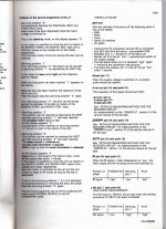
Here's the full service modes available,
With a disc inserted if you only get a few of the 50 mv mentioned in the manual then that suggests that the photo diodes are not receiving the laser light. Maybe it's not focusing correctly. Perhaps monitor that again with a disc in while it performs a focus search routine in test mode and see if the 50mv swings up and down.
Here's the full service modes available,
Attachments
- Home
- Source & Line
- Digital Source
- Micromega Solo CD Player - help!!