1. Relays are cheap : hunt down some of the electronic surplus stores. I got 40 DPDT relays for NZ 50c each. They'll beat a silicon mux every time.
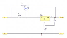
2. Putting regulators in parallel is tricky. Each will need a ballast resistor of about 0.5 ohm, to get them to current share properly. Its better to use a pass transistor as in the diagram below. (Caps omitted for clarity). Use a big, muscley pass transistor and this circuit should be good for 6 amps or so.
2. Putting regulators in parallel is tricky. Each will need a ballast resistor of about 0.5 ohm, to get them to current share properly. Its better to use a pass transistor as in the diagram below. (Caps omitted for clarity). Use a big, muscley pass transistor and this circuit should be good for 6 amps or so.
Attachments
your totally right Kermit, something like that may very much be a possibillity. I'l consider it, but i have a few questions maby you could answer:
1) what is the reason for R1 and R3?
2) C2, C5, C6 and C4 are unipolar? what size? (and purpose.. decoupling)
3) any tips for transistors that might be big enough to meet my requirements?
regards
marius
1) what is the reason for R1 and R3?
2) C2, C5, C6 and C4 are unipolar? what size? (and purpose.. decoupling)
3) any tips for transistors that might be big enough to meet my requirements?
regards
marius
TwoSpoons said:1. Relays are cheap : hunt down some of the electronic surplus stores. I got 40 DPDT relays for NZ 50c each. They'll beat a silicon mux every time.
I really dont know of any such stores here in the vincinity, nor in the whole country really..
guess i'l have to go treasure hunting.. if you know of anyone such store who ship worldwide and you can pay the parcel out at the post office, let me know, ok?
")
if you Google for "electronic surplus" you'll get a huge number of online stores turn up. Most will ship international. I got my relays from Oatley Electronics , but there's many more out there. It can take some time to find what you're after, buts its worth the effort.
Just a quick answer, if you decide to take this route we can do the math.
R1 and R2 are there for current sharing and limiting.
C2 can be a small film cap like 0.1 uF or bigger. C3 can be as high as you can afford. C6 can be a small polar bypassed by a 0,1 uf film. Anything from a few uF up to a few hundreds will probably do fine, as long as it isn’t so big that it triggers the short circuit protection in the regulator.
Any pnp transistor that can handle the dissipation would probably do fine.
Kermit said:Just a quick answer, if you decide to take this route we can do the math.
R1 and R2 are there for current sharing and limiting.
C2 can be a small film cap like 0.1 uF or bigger. C3 can be as high as you can afford. C6 can be a small polar bypassed by a 0,1 uf film. Anything from a few uF up to a few hundreds will probably do fine, as long as it isn’t so big that it triggers the short circuit protection in the regulator.
Any pnp transistor that can handle the dissipation would probably do fine.
Hi!
after a few days considering costs and batteling the flue, I'v desided to go regulated.
I understand the concept of the circut correct i think, but i wonder, is it not better to use a nice big fat mosfet as they have massivly better current handeling than most tranistors?
i altso wonder how i'm going to handel the lm 317hv, as it's packed inside one of those pescy to-39 encloasures, making heatsinking quite a challenge. (artic ilumina thermal compund and superglue should work thoug..
)and any thought on how to regulate the negative rail?
then dont carry the negative counterpart on elfa, where i'm usally bying, and where my school has an account..
but you said something about refering the positive senser off to ground?
thanks so much for your help.
regards
marius
Mosfet, why not?, but you realy don't need that big a transistor.
But why use lm317hv? Only 0,5A, its hard to mount on heatsink, and you will never get even close to 60 volts between in and out voltage.. Use lm317 t instead, a fraction of the price, comes in a easy to mount to220 package, and it handels 1,5 amps...
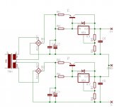
Negative rail, se the image i posted, its right there
edit: just realized you where going for +/-47 volts and lm317t only goes to 35v.
edit again: Just found lm317k on sale, 3 pcs for only 5 NOK!! at http://www.mamut.com/ati see "sluttsalg komponenter". They also have 2-pole relays for only 18 NOK.
But why use lm317hv? Only 0,5A, its hard to mount on heatsink, and you will never get even close to 60 volts between in and out voltage.. Use lm317 t instead, a fraction of the price, comes in a easy to mount to220 package, and it handels 1,5 amps...
Negative rail, se the image i posted, its right there
edit: just realized you where going for +/-47 volts and lm317t only goes to 35v.
edit again: Just found lm317k on sale, 3 pcs for only 5 NOK!! at http://www.mamut.com/ati see "sluttsalg komponenter". They also have 2-pole relays for only 18 NOK.
now, that is cheap, but alas, not what i need. maby i'l pick a few with me when i buy the relays.. regulators are always nice to have, and i need a few for my preamp, i do..
well, i figure, the more headroom for the mosfet\transistor, the less heat dispation, atleast somewhat, and bigger dispachion area.
I altso want to dimmension this thing for the power bursts that a class AB amplefier has. so a max of 10 amps is not ureasonable i would think. the lm38867 has a Imax of 30amps(!) if I remember correct.
I feel a litle confused right now..
http://www.diyaudio.com/forums/showthread.php?s=&postid=525273#post525273
now I understand it that it is it is the difference between the input and the output that is 37V on the lm338? if this is the case then i got those regulators all wrong..
edit2: and if it is the potensial between the input and output that can be adjusted 37v, then it would mean i can get away with teh standard version. but do i have it right this time?
Hehe, i know It pays well to check back once in a wile, somtimes a real bargin like that shows up.
Considering the price elfa takes for the lm317hv maybe you should consider using a power op amp like opa549 instead of the regulator.
Check the datasheet at www.ti.com http://focus.ti.com/lit/ds/symlink/opa549.pdf
scroll down to "programable power supply", I think it should be good for 10A and up to 55Volts
It pays well to check back once in a wile, somtimes a real bargin like that shows up.Considering the price elfa takes for the lm317hv maybe you should consider using a power op amp like opa549 instead of the regulator.
Check the datasheet at www.ti.com http://focus.ti.com/lit/ds/symlink/opa549.pdf
scroll down to "programable power supply", I think it should be good for 10A and up to 55Volts
well, elfa dont carry the opa549 unfortunatly, so i thing i better go with the original plan, that is if my newfound understanding of voltage regulators is correct..
i bought some lm 317k from the page as well, and the relays i need, so really am certain of the path. (i bought some transistors as well, dont remember what they were calles, but they cost like 20kr for 4 of them, so i didnt think before pressing.. they looked beefy though.. fet transistors the page said, witch mean they aren't transistors at really, but mosfets, and up to 500V and some 10 amp or something, witch put them right in the pineacle of my needs realy..
oh, how i love this stuff!
edit: did i nemtion that my GC will now have 40.000uf per channel?
and perhaps if it turns out to be good for the sound, i'l shove in the 52.000uf extra i'v bought as well.
I understand the concept of the circut correct i think, but i wonder, is it not better to use a nice big fat mosfet as they have massivly better current handeling than most tranistors?
Uhh, not necessarily. The pass device is running linear so the heat dissipation will be the same whether you use a BJT or a FET. With a FET the gate threshold voltage is much higher so the dissipation in the current balance resistor (R1 in my schematic) will also be higher.
TwoSpoons said:
Uhh, not necessarily. The pass device is running linear so the heat dissipation will be the same whether you use a BJT or a FET. With a FET the gate threshold voltage is much higher so the dissipation in the current balance resistor (R1 in my schematic) will also be higher.
Yes, you are totally right offcource.
Thinking logical is not my strongpoint when i'm exited, but then, who's is?
the headroom part and the heat dispation i stand for what i'v said thogh.
As for the pre itself:
i'm still very much in the thinking\learning prosess, but what i'v got so far is bass\treble regulation, pulled out of a Grundig amp, lm358 based, caus those are the ones i have lying around, +-12v regulated psu, or so it would appear at the moment.
I was hoping to avoid any caps in the pre, keeping the dcoffset as low as humanly possible.
the gain i'm not certain about yet, but 2.5 seems to be my best guess as of yet, considering that the gain on my power amp is pretty brutal.
any tips, hints or things i should really know before i start making this thing?
regards
marius
edit: just rememberd something:
what is this buffer everyone is talking about? what does it do, how and why?
cheers!
demogorgon said:
what is this buffer everyone is talking about? what does it do, how and why?
Not shure this is the one "everyone" is talking about, but this is why and what:
http://members.ozemail.com.au/~lisaras/design.htm
hmm, i belive this one of those few times i actually found this aspect of audio facinating.. the on paper part that is.
So what i understand out of reading this is that using only a pot somehow "tingles" with the feedbackloop, but by using either a op-amp or a tube with no gain we cut the pot away from the feedback loop, so it cant "tingle" with it any more?
if this is so, then an opamp of quality is needed i think..
well, anyways i'v got a few lm324 and 358 lying here, so i thing i'l give it a shot if i find the correct resistor values.
Is it critical to have the opamp close to the lm38** itself?
regards
marius
sounds good!
I think i'l incorperate it into my lm4700 amp i buildt last night.
p2p and veroboard combined, looks like hell, but i'm positive it'l sound good. all paths are cut as shor as i could, even the caps are solderd on teh legs of the ic. looking forwart to trying it.
regards
marius
Oh, by the way, while i'm draining all knowledge i can on this subject:
what is a DC servo, and why incorperate a "current buffer" after the op-amp?
cheers!
humm.. strugeling to understand that schmatic of yours kermit..
I got the parts needed exept maby for resistor values and the diode's, but the rest shuld be fine..
I would love to do the math with you, or maby you can point me in the right direction? I dont mind thinking for my self, but this a litle above me at teh moment..
regards
marius
I got the parts needed exept maby for resistor values and the diode's, but the rest shuld be fine..
I would love to do the math with you, or maby you can point me in the right direction? I dont mind thinking for my self, but this a litle above me at teh moment..
regards
marius
- Status
- This old topic is closed. If you want to reopen this topic, contact a moderator using the "Report Post" button.
- Home
- Amplifiers
- Chip Amps
- microcontrolled pre for a GC power amp