i have one on my bench, i also replaced the 500 volt caps to fresh ones, instead of the k88's i put in the EL34's instead, i saw no advantage putting in the bigger tube, the bias filter caps is shot so i replaced that too...
this amp required matched quads, there is only one bias adjustment pot...
scratchy volume control will be replaced soon...
this amp required matched quads, there is only one bias adjustment pot...
scratchy volume control will be replaced soon...
"this amp required matched quads"
Or you can, as I did, build individual bias adjustments for V4/V5 on a small perf board. Voltages indicated on the schematic (for cathode voltage) could be a guide for adjustment. I think (long time ago now), I ended up setting the idle current to 25mA per tube. Not sure about this number though.
What I was thinking of doing:
- Turning the amp on, makes the 6 small signal tubes light up like flash lights, some brighter than others, before calming down as they heat up. A rectified, regulated, constant current filament supply would ease this down, as would using a simple (small value) resistor in series with the filaments.
and/or:
- Include a thermistor in series with the primary of the power supply, as per Nelson Pass, used in the diy F4/F5 etc. amps.
/Urban
i have had happy experience with JJ 6L6GC quads that i purchased, the cathodes had individual cathode resistors, so it turned our that the bias voltage were exact up to the first decimal place....can you dig that?
edit: an NTC in the primary of the power traffo is a good idea imho...i even use those in series with the filament supply if i wanted to lose a few millivots...
edit: an NTC in the primary of the power traffo is a good idea imho...i even use those in series with the filament supply if i wanted to lose a few millivots...
No need to worry about, Urban!What I was thinking of doing:
- Turning the amp on, makes the 6 small signal tubes light up like flash lights, some brighter than others, before calming down as they heat up. A rectified, regulated, constant current filament supply would ease this down, as would using a simple (small value) resistor in series with the filaments.
Have a close inspection of these tubes and most probably you will find some uncoated parts of the filament between the weld and it's entry into the cathode tube. It's exactly this part that lits up heavily, due to it's small thermal capacity.
Best regards!
Hi Nrik,
Out of interesr, what fault were you fixing?
What output tubes did you have?
Rgds, Richard
One of the output transformers and the mains transformer were defective (shortcircuited). I was lucky to be able to get 3 new original transformers from Papworth Audio in the UK.
For new tubes I chose JJ/Tesla, because I found out it is the brand Tim de Paravincini uses today selected and rebranded to EAR Yoshino, and also because I read they had a neutral sound compared to other brands.
I am planning on replacing the old electrolytics in my TVA10, since they will be pushing 50 years now. I was looking at this description of updating an EAR509 by Patrick Turner ...
EAR509 reformed
... and he replaced the 22uF 500V electrolytics that are part of the crosslinking between the windings on the OPT with 2uF polypropylene capacitors.
"The OPT anode and cathode windings are not bifilar wound as in McIntosh, using triple insulated wire because there is 470Vdc between the two windings. The two windings do not need to be bifilar wound, because the leakage inductance between the two windings can be eliminated by use of shunt C across ends of anode and cathode windings with the same phase and amplitude of Vac. EAR used 22uF elcaps, but I found 2uF plastic caps were entirely adequate."
It would be nice to reduce the number of electrolytics. Wondering if any of the more experienced around here have any views on this modification.
I was given one as well. I cant remember whether it was a TVA-1 or 10. I was told that TVA meant Tim's Valve Amp and he designed both but Im not sure about that. The pcb showed lots of evidence of burn marks and repairs and it did show the oscillation problems mentioned.
So while it did sound rather good with nice tight bass I decided to pass it on. Maybe thats how I got it. Good Luck.
So while it did sound rather good with nice tight bass I decided to pass it on. Maybe thats how I got it. Good Luck.
My understanding was that the TVA-1 was flaky, whereas the 10 was solid. I've had no issues with mine other than when I bought it, second hand, it had a hum issue depending on which way the 2 prong AC plug was oriented. I changed the wiring to a properly grounded AC line and that cured it.
. I was told that TVA meant Tim's Valve Amp and he designed both but Im not sure about that.
I think the TVA means Thermionic Valve Amp.
I believe the TVA10 (EL34 amp) is a pure Tim de Paravicini design.
Tim was a co-designer of the TVA1 (KT88 amp), which is a much simpler design.
I much prefer the TVA1, but Tim would not agree.
Tim About the TVA1:
Tim de Paravicini Page 3 | Stereophile.com
why would anyone design a tube amp to replicate solid state?
i like my tube amps sounding like a tube amp....
Hi Easyrider82, I was about to ask the same question. Mine is working fine after a recap, and I left the bias unchanged. It is currently 39v. However I'd like to measure the current through the tubes, and add a current sense resistor somewhere. Presumably a 10ohm resistor would not hurt between the cathode and cathode winding in the OPT? Or is there a better approach?
What are the hazards that are brought by that arrangement? I was a bit concerned to be adding 20ohms resistance on the cathode winding, so am gravitating towards 1ohm resistors.
I noticed too that the small tubes are all a bit starved in their heater supplies. 3 tubes are supplied serially in 2 chains from a 36v winding, 33.5v in my case, and they are not equally dropping the same voltage. The first tube in each series chain flashes very brightly on startup.
The supply where I live is 230VAC, and the power transformer had a 240v tap, so I have switched to that in order to get B+ to be 485v, which is a bit kinder on the 500v electrolytics.
Hi Easyrider82, I was about to ask the same question. Mine is working fine after a recap, and I left the bias unchanged. It is currently 39v. However I'd like to measure the current through the tubes, and add a current sense resistor somewhere. Presumably a 10ohm resistor would not hurt between the cathode and cathode winding in the OPT? Or is there a better approach?
HI OldHector,
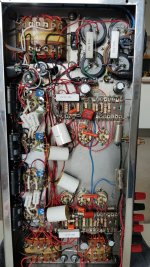
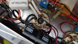
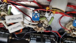
i'm sorry but i have no idea where to measure the bias voltage/current. my amp has been modified from the previous owner (replaced rotten pcb with air cabling and added single potentiometers for every EL34 to regulate bias, other than some recap).
The circuit should be identical to the old one (can't verify by myslef).
Would you kindly please help checking the correct bias value here?
Despite of the mess you can see, it sunds really good!
I'll post a few pics of the actual situation.
Thank you in advance.
Attachments
- Status
- This old topic is closed. If you want to reopen this topic, contact a moderator using the "Report Post" button.
- Home
- Amplifiers
- Tubes / Valves
- Michaelson & Austin TVA 10