OK, I think i have a plan!
Looking at the Pi 3B+ I do need to keep the 1.2v and the power is distributed around the Pi like this:
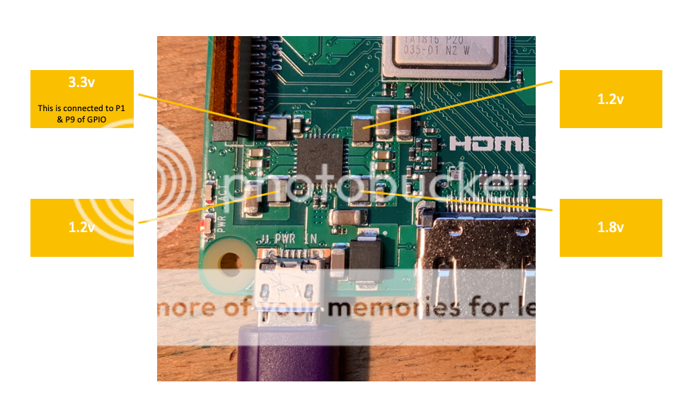
So, my plan is to remove the inductors for the 3.3 and the 1.8 then directly solder connection from the mezzanine 1.8v output to the 1.8v inductor pad (the one that isn't connected to the DC/DC chip).
Looking at the Pi 3B+ I do need to keep the 1.2v and the power is distributed around the Pi like this:
So, my plan is to remove the inductors for the 3.3 and the 1.8 then directly solder connection from the mezzanine 1.8v output to the 1.8v inductor pad (the one that isn't connected to the DC/DC chip).
This should explain why you won't be able to do anything about it: More power to your Pi - Raspberry Pi
Short version - the chip not only supplies the rails but measures the supplied voltage/current and is controlled by the RPi firmware, so when the firmware doesn't see the readings it expects from the chip it doesn't boot...
I guess you could modify the firmware and bypass the monitoring logic.
Short version - the chip not only supplies the rails but measures the supplied voltage/current and is controlled by the RPi firmware, so when the firmware doesn't see the readings it expects from the chip it doesn't boot...
I guess you could modify the firmware and bypass the monitoring logic.
Just parallel 4 of his twin lt3045 boards, it's easy. I use 2 pairs for my Brooklyn psu.
Yes, but I thinks 2 pairs must equal Voltage outputs. And if it made in a intergrated board better for us because wires shorter ànd less noise.
(unfortuanly) i found the answer ... the raspberry pi 4 seems to use a "all in one" chip that offers the different voltage rails which also communicates with the kernel drivers over i2c, so its not easy to replace it
i wonder if placing carefully capacitors to the inductors (either before or after the inductor and the other end to ground) could atleast improve the voltage rails of the switching voltage regulators inside this chip, it will probably never reach linear regulator teretory but maybe it will get closer
i have to research this a little since im not too keen on circuit design but it should be possible to make a little "adapter board" with capacitors placed on it and hooking wires to either end of the inductor and finding a good grounding point (any help would be much appreciated") )
)
i wonder if placing carefully capacitors to the inductors (either before or after the inductor and the other end to ground) could atleast improve the voltage rails of the switching voltage regulators inside this chip, it will probably never reach linear regulator teretory but maybe it will get closer
i have to research this a little since im not too keen on circuit design but it should be possible to make a little "adapter board" with capacitors placed on it and hooking wires to either end of the inductor and finding a good grounding point (any help would be much appreciated
)- Home
- Source & Line
- PC Based
- Mezzanine Power board for Raspberry Pi