Thank you for all the help Salas. Found the bastard ")
While building the DCB1, I only sampled one of the resistors in the package to be correct. Seems there was actually ONE wrong resistor and this one was soldered onto the PCB. Instead of the 47k I had around 800R, thus the BC517 and 550 got damaged.
After exchanging those 3 parts as you suggested, I get an Offset of -1.7mV and -1.2mV.
Seems ok?

I also managed to solve my V+ issues I had a few weeks back. It was Q6 (closest to A/C input). I thought I had changed Q6 but there was bit of confusion about schematics at the time. Now both voltages are a bit below +-10V with 6mV mismatch. I can live with that
Regards
Regards
2SK170 vs LSK170
Hi
Building a Mez on blue PCB. I have 10 2SK170s and 8 LSK170s.
Now, Murphy being ever-vigilant, I have one good pair of 2SKs at 7,79/7,80 and a not so good pair at 10,29/10,33. There's not a single close match among the LSKs. Earlier in the thread it was advised to use closely matched buffer pairs, so I would like to know if these are too far apart - I also seem to remember that IDSS over 10 mA was unwise.
On the other hand, if I can mix and match among both 2SKs and LSKs, I can make a nice pair of an 9,02 2SK and a 9,04 LSK. Is the LSK170 a true clone of the 2SK170?
Thankful for advice!
Lithos
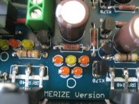
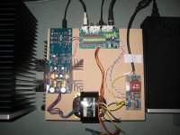
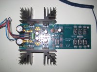
Some pictures of my build so far...
I tried to match every component to the best. Have a lot of 2SK170's so why not
Also hot-rodded it a bit
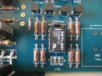
I used matched JFets for the positive and negative shunts. Also matched all the LED's with their corresponding JFet in that position in the circuit.
For the four matched JFets in the buffer section I used for the left channel two 2sk170's with 7,67 and 7,68mA Idss with the same date code '2I' which gave me an offset of 0.0mV
For the right channel I used two JFets from different date codes with Idss of 7,82 and 7,83 but when warming up the offset seems to get worse, and it ended up to 3,5 mV. So I changed them for two JFets with the same date code of '1H' and Idss of 7,88 and 7,80mA which results in an offset of 0,4mV warmed up.
I can get a better matched pair, and so probably better offset, but then the difference in Idss for the left and right channel will be much larger.... but if that's a problem???
Oh, and I did the 'leg-trick'.
The results:
+ Vout= 9.88V and current through R1 ( 10 Ohm/2W) = 175mA
- Vout= 9.85V and current through R1 ( 10 Ohm/2W) = 178mA
Offset left: 0mV
Offset right: 0.4mV
Sound: Perfect! I can not hear a difference between this remote controlled DCB1 or a straight interlink
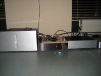
In the pictures you see the DCB1 between my DDAC1794 and my F5Tv3.
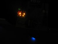
Nice thing is, because I used orange and yellow LED's, it is giving a nice tube filament like, glow in the dark
@Salas; THANKS for all your effort and support !
I listened a few days to the not 'leg-tricked' version with around 0,5 Volt difference between + and -.
What should I have heard in difference? Some more second or third harmonics? Some warmer sound?
Asked by someone without 'golden ears' I don't hear it.....
Walter
I tried to match every component to the best. Have a lot of 2SK170's so why not
Also hot-rodded it a bit
I used matched JFets for the positive and negative shunts. Also matched all the LED's with their corresponding JFet in that position in the circuit.
For the four matched JFets in the buffer section I used for the left channel two 2sk170's with 7,67 and 7,68mA Idss with the same date code '2I' which gave me an offset of 0.0mV
For the right channel I used two JFets from different date codes with Idss of 7,82 and 7,83 but when warming up the offset seems to get worse, and it ended up to 3,5 mV. So I changed them for two JFets with the same date code of '1H' and Idss of 7,88 and 7,80mA which results in an offset of 0,4mV warmed up.
I can get a better matched pair, and so probably better offset, but then the difference in Idss for the left and right channel will be much larger.... but if that's a problem???
Oh, and I did the 'leg-trick'.
The results:
+ Vout= 9.88V and current through R1 ( 10 Ohm/2W) = 175mA
- Vout= 9.85V and current through R1 ( 10 Ohm/2W) = 178mA
Offset left: 0mV
Offset right: 0.4mV
Sound: Perfect! I can not hear a difference between this remote controlled DCB1 or a straight interlink
In the pictures you see the DCB1 between my DDAC1794 and my F5Tv3.
Nice thing is, because I used orange and yellow LED's, it is giving a nice tube filament like, glow in the dark
@Salas; THANKS for all your effort and support !
I listened a few days to the not 'leg-tricked' version with around 0,5 Volt difference between + and -.
What should I have heard in difference? Some more second or third harmonics? Some warmer sound?
Asked by someone without 'golden ears'
I don't hear it.....Walter
Attachments
Hi
Building a Mez on blue PCB. I have 10 2SK170s and 8 LSK170s.
Now, Murphy being ever-vigilant, I have one good pair of 2SKs at 7,79/7,80 and a not so good pair at 10,29/10,33. There's not a single close match among the LSKs. Earlier in the thread it was advised to use closely matched buffer pairs, so I would like to know if these are too far apart - I also seem to remember that IDSS over 10 mA was unwise.
On the other hand, if I can mix and match among both 2SKs and LSKs, I can make a nice pair of an 9,02 2SK and a 9,04 LSK. Is the LSK170 a true clone of the 2SK170?
Thankful for advice!
Andrew could reply that more securely since he had been matching LSKs in the past and has experience on those.
NicMac has measured both and I thought the LSK has lower Yfs than the original Toshiba's. But if that's a problem for this buffer?
I think not, especially if you use the LSK part as the CCS JFET.
I would mix the LSK with the 2SK.If used like you say, no. Not a problem.
One device is working as a CCS the other device is working as a Source Follower.
Use the slightly lower Idss as the CCS device. This will give a tiny negative output offset.
Read Dennis Feucht if you want to minimise the output offset and equalise the Id for slightly different pairs.
If you were building a differential input LTP pair then I would be using accurate "matching" for that duty.
the B1 and the DCB1 do not need matching. Just select similar Idss.
When I measure my leds from 9 V and through a 1 K Ohm resistor, most of them are in the 2,8 -2,9 V range. To get as close as possible to 9V and 5,4 V can I short one and use 4 instead of 5 and 2 instead of 3??
Hotroadingon diyAdudio standard Mezemerize PCB): One member mention that two 100uF should be be changed to 100 nF. Is that correct?
Eivind Stillingen
Hotroading
on diyAdudio standard Mezemerize PCB): One member mention that two 100uF should be be changed to 100 nF. Is that correct?Eivind Stillingen
You need normal LEDs that are low noise. Your range indicates super bright or blue. Those can be noisier. Just buy a small bag of red generic from a store very cheaply.
Keep all four 100uF is the original configuration, but don't experiment with the last ones near the end of the regulator for sure.
Keep all four 100uF is the original configuration, but don't experiment with the last ones near the end of the regulator for sure.
Hello everyone. And, lots of thanks to Salas for his design, as well as to Pass for the original circuit.
I'm new here, but have watched this forum for a long time. I have already built a Gainclone using Daniel Peter's kit and instructions, and now I'm finalizing a Mesmerize.
For this, I have a question regarding the voltage on the 68R pair of resistors - this came up when measuring them for increasing the current above 200mA. On one side, I have 1.59V, while on the other side I measure 1.52V. After replacing these resistors with 10R, I measured 1.36V, respectively, 1.18V. I am still not at the desired level for the current, but I am already concerned about this difference between the voltages.
However, listening to the preamp while using the cold 2x68R per side, it sounds very nice, and I couldn't hear anything wrong.
Can, please, somebody tell me why I have this difference, and how can it be corrected (if needed)?
Thank you.
Salas, thank you very much for your answer. I wasn't sure that doing so is good. I will use a 5R5 on the weaker side, and a 6R4 on the other one. So, both sides will be around 212mA.
I know you heard it an awful lot of times, but I need to say myself that I really like your design. At 200mA it simply spreads the instruments apart and the imaging is blooming. It is an excellent addition to my systems (under development).
I know you heard it an awful lot of times, but I need to say myself that I really like your design. At 200mA it simply spreads the instruments apart and the imaging is blooming. It is an excellent addition to my systems (under development).
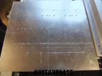
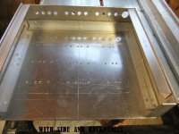
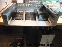
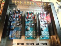
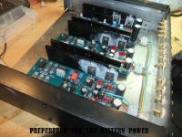
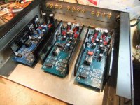
Here is the results of this week-ends building Mezmerize for six channels. This unit might, if the listening results will be what I hope for, "take the place" to my six channels Copland CVA 306 (tube) in my system. It will be hotrodet with a power in its own chassis(4x18000 uF/200VA trans.) I have ordered six attenuators (20 Kohm).
Eivind Stillingen
Eivind Stillingen
Attachments
- Home
- Amplifiers
- Pass Labs
- Mezmerize DCB1 Building Thread