Pass DIY Addict
Joined 2000
Paid Member
I've been reading DCB1 threads for what seems like a long time now and have a question about the bias setting. I have most of the parts and will begin assembly soon.
My plan is to build a hot rod version of the Blue Mesmerize board, somewhere in the 400-600mA range. The irfp240 and 9240's will be adequately sinked, but can someone please explain to me how this affects the output sound quality? Where does this extra bias current "go"? In my Aleph-x amps, the extra bias through the output devices improves sound quality, but I don't see how the 170s in this design can pass the extra current...
I'm sorry if this is a basic question or this was described before - I didn't find a description of this in my reading.
Thanks in advance!
It doesn't get used. It's essentially mostly waste heat. Same is true for the most part for the Aleph-X, however they are biased directly.
In this case, the power supply is rev'd up to potentially give a lot of ma, but it uses very little, taking only what it needs. Subjectively it sounds better. Making the soundstage a little more sweet and also solidified in my experience.
In this case, the power supply is rev'd up to potentially give a lot of ma, but it uses very little, taking only what it needs. Subjectively it sounds better. Making the soundstage a little more sweet and also solidified in my experience.
Pass DIY Addict
Joined 2000
Paid Member
Thanks Tea-Bag, this makes sense to me. I was going crazy trying to figure out how increasing the bias would alter the output in this case...
I'm trying to plan out the physical configuration now. I'm planning a stand alone preamp using the DCB1 + Lightspeed attenuator and was thinking about building a DAC into it as well. So many choices...
I'm trying to plan out the physical configuration now. I'm planning a stand alone preamp using the DCB1 + Lightspeed attenuator and was thinking about building a DAC into it as well. So many choices...
Would someone update the BOM to account for EOL products such as the recommended relays?
This is what has been recommended in the past: NEC EA2-12NJ
http://nl.mouser.com/Search/ProductDetail.aspx?R=EA2-12NJvirtualkey55100000virtualkey551-EA2-12NJ
Fully compatible and equal quality if not better. NEC has great rep for small relays.
I am currently building a Mezmerize buffer to (possibly) serve as a new pre in my system.
I voted for the Mezmerize because of the input option.
Having read a fair bit on the threads (including DCB1) I am planning to sort of hot rod my Mez a bit... current set resistors are two 12Ohm in // (for about 275mA?), diodes are HFA08TB60 (had them in my drawer), semis will be heatsinked to the bottom of the future case via two solid aluminum rods, and the input capacitance will have some hefty assistance by off board fellows.
There is still a few parts missing, and I've got two questions: I was planning to substitute the two first 'lytics in the regulators with film caps, but space is rather limited. So I could mount some decent film cap off board, or just use 'lytics also. How sensitive is this to sonics (subjectively") ), and how critical is the value? I have 47uF 50V and 1000uF 25V (again both in the drawers)...
), and how critical is the value? I have 47uF 50V and 1000uF 25V (again both in the drawers)...
And then there is the 10R under one of the K170's on the board: I read in the other thread that this one has to be changed to 1R. Is this mandatory (because the 10R are already soldered in...? and I hate desoldering
I voted for the Mezmerize because of the input option.
Having read a fair bit on the threads (including DCB1) I am planning to sort of hot rod my Mez a bit... current set resistors are two 12Ohm in // (for about 275mA?), diodes are HFA08TB60 (had them in my drawer), semis will be heatsinked to the bottom of the future case via two solid aluminum rods, and the input capacitance will have some hefty assistance by off board fellows.
There is still a few parts missing, and I've got two questions: I was planning to substitute the two first 'lytics in the regulators with film caps, but space is rather limited. So I could mount some decent film cap off board, or just use 'lytics also. How sensitive is this to sonics (subjectively
), and how critical is the value? I have 47uF 50V and 1000uF 25V (again both in the drawers)...And then there is the 10R under one of the K170's on the board: I read in the other thread that this one has to be changed to 1R. Is this mandatory (because the 10R are already soldered in...? and I hate desoldering
Attachments
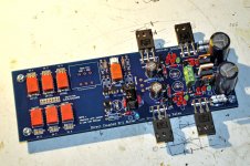
Use 100uF (47uF are also acceptable) on the first caps positions now void on your PCB. One thing that works nicely is 220nF COG + 0.33R SMD parts snubber directly on its leads at flip side. DON'T do that on the output lytic. Also 10R to 1R ain't mandatory. I have "voiced" the MEZ using different subtleties than in the HYPNO which is poised for the heavier running aspirations so you may experiment but don't draw directly from HYPNO users experiences word for word. 12//12 Ohm is as far as I would go minding the main electrolytics ability & the bridge diodes best ventilation mounting and temp for reliability. Which is already taken care of in yours by substituting with TO-220s as I see. Good luck then.
Hello everybody , this is going to be my first post here , after reading a lot . I'm going to use also IRFP244 because has a bunch of them after finish Aleph2Would there be any ill effect if I use IRFP244 instead of IRFP240?
Theoretically no. But I haven't used it.
I hope you are right on this and before any question , want to thank you for this great design and all the help that you provide to people with little knowledge like me. Thanks in advance and I have some photos of the building process.
Attachments

This is what has been recommended in the past: NEC EA2-12NJ
EA2-12NJ NEC | Mouser
Fully compatible and equal quality if not better. NEC has great rep for small relays.
That's what I got, but it's sort of frustrating to sit at the computer with the BOM, copying and pasting numbers into Mouser's search, only to have the search come up with discontinued products. The BOM, which is linked from DIY's store, should be reasonably current.
Whoever wants to revise the BOM in Excel with new Mouser links, high price parts extra column etc. he can post it and I will see to review it, send it over, and change it around in the initial posts here. The original is not an editable doc and a new one should be done from ground up.
Does some as in all comparable situations. Keeping the wiring loop shorter by using extension rod is smaller loop area for the signal travel. But not that noticeable at line level no gain like in this one.The selector wiring is irrelevant, carries no signal. 20K switch pots are more focused than an ALPS but to offer enough smoothness and gradation is not easy for little cash models. Vishay low ppm brown resistors are also excellent for the 220 Ohm, 220K, 1Meg positions if you aim rather neutral when Takman carbon are preferred if you aim rather warmish depending on how the rest of your system already behaves tonally.
- Home
- Amplifiers
- Pass Labs
- Mezmerize DCB1 Building Thread