There are likely more 9640s than 640s (the amp may use 540s and 9540s if the rail voltage is less than ±50v).
All of the source legs for the 9640s will be connected directly (~0 ohms) to the center leg of the positive rectifier.
The source legs of the 640s will be connected to the center leg of the negative rectifier.
All of the source legs for the 9640s will be connected directly (~0 ohms) to the center leg of the positive rectifier.
The source legs of the 640s will be connected to the center leg of the negative rectifier.
Ok cool thank you perry.
! more question i was checking the driver board and a transistor marked a1023 has a leg broke off it Wondering what the part number is thata i need to order . Or can i sub this part for a differnt one ?? I have alot of a916 but not sure its the same
! more question i was checking the driver board and a transistor marked a1023 has a leg broke off it Wondering what the part number is thata i need to order . Or can i sub this part for a differnt one ?? I have alot of a916 but not sure its the same
The 2SA916 is not a suitable substitute.
The original (KTA1023 or 2SA1023) is difficult to find.
If you have a 2n6491, you can use that but you'll have to install it facing the opposite direction since the pin configuration is reversed.
I use the 6491s as replacements for the 2SA1266 drivers also when there is sufficient clearance. Sometimes, I have to cut the tabs off of the transistors to make them fit.
You should not be blowing FETs. If you clamp the FETs to the sink and either use a current limiter or a 10 amp fuse, you're unlikely to ever blow another power supply FET.
Did you check the drive signal before installing the FETs?
Have you checked all of the gate resistors?
Did you check the drive signal before installing the FETs?
Have you checked all of the gate resistors?
Since some of the FETs are blown, remove all of them.
Set the timebase to 10uS.
Set the vertical amplifier to 5v/div.
When you touch the probe to the chassis ground, do you get a straight line trace with no vertical deflection (the trace remains at the reference line)?
When you touch the probe to the B+, do you get a straight line trace that's deflected ~2.5 divisions above the center reference line?
Ok im gonna try that in a few . But wondering in the driver board There are transistors mared c3198 and a1266 But then just one of them is that 1023 wondering if that belongs or did someone put it there in place of something . Since it had a broken leg on it and it looks as if someone soldered it there
I did the test with my scope and everything u said looks ok . On the negative i had a straight line and on the positive i had a line that was deflected 2.5 above the line. As soon as i put the fets in and clamp them to the heat sink/And apply remote voltage the fets blow with 2 secs they catch on fire.
Wondering what my next step might be?
Wondering what my next step might be?
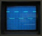
With the FETs out of the circuit, touch the scope probe to the gate pad for each of the FETs. You should see a square wave that goes from ground (reference line) to ~10v (2 divisions) The rising and falling edges should be vertical. It's especially important that the falling edge (right-side edge) goes very nearly back down to the reference. It should look something like the attached photo.
Is this what you have on all 8 gate pads?
Is this what you have on all 8 gate pads?
Attachments
Ok some more checking into this amp. I believe the power supply fets are IRFZ44E. The outputs are as followed the first 2 closet to the rca jacks are
Irf640 then the next 4 are IRF9640. Then there is board locations marked U52 and U51. In U52's spot there is KIA 7915PI But in U51's spot the part has been cut off the board. Wondering what part goes there any help would greatly be apeericated
Irf640 then the next 4 are IRF9640. Then there is board locations marked U52 and U51. In U52's spot there is KIA 7915PI But in U51's spot the part has been cut off the board. Wondering what part goes there any help would greatly be apeericated
- Status
- This old topic is closed. If you want to reopen this topic, contact a moderator using the "Report Post" button.
- Home
- General Interest
- Car Audio
- Memphis 16-ST500D