Tried other transistors (not the exact ones) and some other things and my model still oscillates. Could you try some newer transitors (bc56o) to see if you can get it to oscillate? Wonder why the 2 sims differ here? I have a theory that this amp is bootstraped to the front end and without the tape head impedance (which is inductive and should have a resonant freq with the input cap?) loading down the positive feedback the thing oscillates. I need to do some more simming (is that a word?).
Some other things Ive learned. I think that besides gain the circuit provides a huge bass boost EQ that you will have to copy if you try to reproduce this circuit with an opamp.
I wonder if this thread should be moved to the solid state forum where there is more interest in transistor circuits. This is an interesting design with the complicated feedback.
Yes, I can do that.
I have tried nearly every model I have for the PNP and the only thing that seems to change are shifts in the voltage operating pionts in the last stage.
So I will try some more NPN's aswell.
I did try to put a jfet on input stage but it did not work and requires a complete redesign with to many modification to make it work,so, I scrapped that idea.
It is a strange type of circuit that was commonly used in such preamp apps.
I didn't understand it until I found it in one of my text books and they labeled it as " the positive feedback method".
I will make an effort and try to find it.
It is probably sitting right on the edge of oscillation in order to get such a high gain with a low impedence low level signal.
What bothers me most is not the low frequency hump, But the way the frequency response changes when the output load resistor gets below 10k ohms.
Which is why I had asked for a confirmation of the component values.
As this value is missing from the original schematic.
Once the frequency response is determined the rest is a piece of cake. jer
I wonder why these 2 different sim programs give different results! The caps on the output make it an EQ if the load is right.
Commonly called bootstrapping. Adds gain, decreases stability.
From my initial sims the freq response looks like a low pass filter with a cutoff of 10hz till about 1khz where it flattens out about 40-50 db below 10hz (extreme EQ ) looks sorta like RIAA eq till 1khz. Dont know if this is standard tape head EQ or not but this is what you will want to reproduce in a substitute circuit.
I didn't understand it until I found it in one of my text books and they labeled it as " the positive feedback method".
Commonly called bootstrapping. Adds gain, decreases stability.
Once the frequency response is determined the rest is a piece of cake. jer
From my initial sims the freq response looks like a low pass filter with a cutoff of 10hz till about 1khz where it flattens out about 40-50 db below 10hz (extreme EQ ) looks sorta like RIAA eq till 1khz. Dont know if this is standard tape head EQ or not but this is what you will want to reproduce in a substitute circuit.
YES, NAB or IEC is similar but it is supposed to start at 3150hz then it was moved to 4500hz and then finaly 6300hz.
MY sims show to be around 6khz to 8.5khz.
My link in post #54 is a discussion of the equelization curves adapted by the industry by the inventors themselves.
It is a very intresting read.
Since the tapes themselves are created on standard tape machines (that I know of) an IEC eq curve is probably all that is needed.
The only question is which frequency standard should be used?
But this can be switchable very easliy. jer
Last edited:
The IEC EQ current as of 1970. That would be all the Mellotrons.
They didn't change the tape EQ because they had to service all the machines in the field. If you have a spare tape frame, you can change the tape set in about 3 minutes. So bands had multiple tape frames. I barely missed getting a used case for my spare frame that was used by Tangerine Dream.
They didn't change the tape EQ because they had to service all the machines in the field. If you have a spare tape frame, you can change the tape set in about 3 minutes. So bands had multiple tape frames. I barely missed getting a used case for my spare frame that was used by Tangerine Dream.
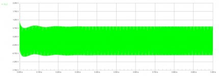
Played with the sim some more. Found you could get rid off the oscillation, reduce the ringing by increasing the positive feedback resistor to 240K-250k. Decreaeses the gain at 10 hz (which is useless anyway). Dosnt seem to effect the rest of the freq response.
I still think the input loading of the tape head will make a big difference in the response of this cct.
I still think the input loading of the tape head will make a big difference in the response of this cct.
I have tried many different types of transistors and none of them seem to make any diifference.
Except however some high HFE types do seem to cause the ringing to last a few cycles longer than others, But have not set it into oscillation.
I have not tried increasing the gain yet to find out.
Right now I'm trying to determine what the freqeuncy curve is.
It apears to be either IEC at 6300hz or possibly a duplicating standard which is flat with a slight roll off about 3db at 12.5khz.
It is very diffucult for me to figure this out as circuit maker does not have a db scale option on th AC analysis function. jer
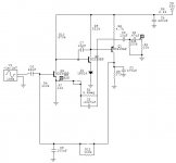
The 221K resistor at the input is a bias circuit for the input stage. The network that feeds its voltage should have no audio on it- however I think they may have cut off the timing constant a little too high. If you are doing sims, try doubling the value of the 220uf cap. I have also thought about using two 110K resistors in series, rather than the single 221K, with a 100uf cap to ground in the middle to help filter out audio signals.
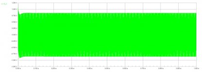
Here are the sims of the mods you had suggested.
Changing the 220uf cap made no difference but the extra filtering seemed to help.
But I still can't tell if it will make any effect on the noise figure.
I was reading about a tape preamp mod and they mentioned using another type of transistor other than a 2N2907 for lower noise but no details on the circuit as they were trying to sell something that cost way less than what the where asking for it.
I will get that link and post it as there was some good info aswell on tape eq. jer
P.S. Here is the link,
http://www.bottlehead.com/et/adobespc/Seduction/bottleheadtapeheadpreamp.htm
Attachments
Last edited:
The 221K resistor at the input is a bias circuit for the input stage. The network that feeds its voltage should have no audio on it-
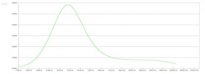
If it where only for bias it would not be atached to the output. This looks like positive feedback to increase the low end gain. Does that second plot say the peak is 8000v?
Just trying to figure out how to post my results, maybe they will help clear things up.
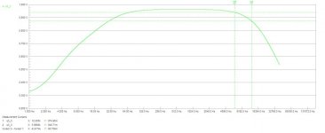
These results are taken from the collector of the output trany.(the output filter dosnt change it very much. The responses shown are for 3 different values of the bootstrap resistor 200k 220k 230k , the only stable one is 230k and its f response is only slightly different below 100hz.
The input is -40db so the 1khz gain is 58db the 10hz gain is 100db!! This f response is riduculous. Why would you need 30db more gain at 10hz than at 20 hz when its totally inaudable. I still think the circuit response would be different with the tape head inductance atached to the input.
The input is -40db so the 1khz gain is 58db the 10hz gain is 100db!! This f response is riduculous. Why would you need 30db more gain at 10hz than at 20 hz when its totally inaudable. I still think the circuit response would be different with the tape head inductance atached to the input.
- Status
- This old topic is closed. If you want to reopen this topic, contact a moderator using the "Report Post" button.
- Home
- Live Sound
- Instruments and Amps
- Mellotron preamp schematic