Background:
Recently I purchased an amazing low cost SET integrated amplifier: MP-401 EL156 Integrated Amplifier [MP-401] - $599.99 : Musical Paradise - Audio Art . It's the first SET I owned or listened to and I'm highly impressed by it's sound quality, which, as I understand, is to be expected from good SET amps.
Alas, this amp with it's declared 15Watt doesn't have enough power to drive my speakers to their full ability. Also, in high listening volume it distorts.
I guess I need about 30-50 Watt. Commercial SET amps of such power are way beyond my finances. Being retired, I just cannot buy a commercial one. So, I'll have to build one myself.
The Musical Paradise MP-401 comes with Chinese EL156 and I like their sound very much. I tried Chinese KT88 and Russian (SED) 6550 on this amp and a Push-Pull one and I didn't like their sound. So, the amp I'm going to start with will be based on the Chinese EL156. In order to get more power I'll have to use parallel output tubes.
Question:
Since I have zero experience with SET amps, I'd like to hear from you, experienced DIY'ers: when all else is equal, should I expect degradation of performance when parallel OP tubes are used in a SET amp? (Yes, I'm aware of the fact that the amp's sound quality will be up to the OP trafo used).
Basic decisions:
1. HT of about 420-450 Volt (for maximum OP power).
2. Class A1 operation (for purest sound).
3. Very little local negative feedback (for somewhat reducing harmonic distortion without big undesirable impact on the sound).
The options:
Right now I see 3 basic options:
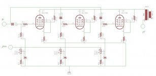
Option 1: Fixed bias from regulated negative supply, adjusted individually for each one of the 3 OP tubes.
Benefits:
A. Avoiding the dreadful capacitor necessary for cathode bias.
B. Maintaining equal quiescent current for each one of the 3 OP tubes.
Drawbacks:
A. Should the bias voltage change or fail, the OP tubes will burn out.
B. Higher parts count than on the other options, especially input capacitors.
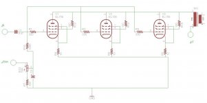
Option 2: Fixed bias from regulated negative supply, adjusted to bias shared by all 3 OP tubes.
Benefits:
C. Avoiding the dreadful capacitor necessary for cathode bias.
D. Lowest parts count.
Drawback: Should the bias voltage change or fail, the OP tubes will burn out.
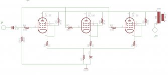
Option 3: Cathode bias, shared by all 3 OP tubes.
Benefits:
E. The conventional method usually used in Class A1 SET OP amps, safe for the OP tubes.
F. Low parts count.
Drawback: the dreadful capacitor necessary for cathode bias.
All comments and suggestions are welcomed.
Recently I purchased an amazing low cost SET integrated amplifier: MP-401 EL156 Integrated Amplifier [MP-401] - $599.99 : Musical Paradise - Audio Art . It's the first SET I owned or listened to and I'm highly impressed by it's sound quality, which, as I understand, is to be expected from good SET amps.
Alas, this amp with it's declared 15Watt doesn't have enough power to drive my speakers to their full ability. Also, in high listening volume it distorts.
I guess I need about 30-50 Watt. Commercial SET amps of such power are way beyond my finances. Being retired, I just cannot buy a commercial one. So, I'll have to build one myself.
The Musical Paradise MP-401 comes with Chinese EL156 and I like their sound very much. I tried Chinese KT88 and Russian (SED) 6550 on this amp and a Push-Pull one and I didn't like their sound. So, the amp I'm going to start with will be based on the Chinese EL156. In order to get more power I'll have to use parallel output tubes.
Question:
Since I have zero experience with SET amps, I'd like to hear from you, experienced DIY'ers: when all else is equal, should I expect degradation of performance when parallel OP tubes are used in a SET amp? (Yes, I'm aware of the fact that the amp's sound quality will be up to the OP trafo used).
Basic decisions:
1. HT of about 420-450 Volt (for maximum OP power).
2. Class A1 operation (for purest sound).
3. Very little local negative feedback (for somewhat reducing harmonic distortion without big undesirable impact on the sound).
The options:
Right now I see 3 basic options:
Option 1: Fixed bias from regulated negative supply, adjusted individually for each one of the 3 OP tubes.
Benefits:
A. Avoiding the dreadful capacitor necessary for cathode bias.
B. Maintaining equal quiescent current for each one of the 3 OP tubes.
Drawbacks:
A. Should the bias voltage change or fail, the OP tubes will burn out.
B. Higher parts count than on the other options, especially input capacitors.
Option 2: Fixed bias from regulated negative supply, adjusted to bias shared by all 3 OP tubes.
Benefits:
C. Avoiding the dreadful capacitor necessary for cathode bias.
D. Lowest parts count.
Drawback: Should the bias voltage change or fail, the OP tubes will burn out.
Option 3: Cathode bias, shared by all 3 OP tubes.
Benefits:
E. The conventional method usually used in Class A1 SET OP amps, safe for the OP tubes.
F. Low parts count.
Drawback: the dreadful capacitor necessary for cathode bias.
All comments and suggestions are welcomed.
Attachments
Josh,
Given your financial restraints for this project, you may first want to explore the cost of 15-30 watt SE output transformers.
That much I believe I can afford.
You already have a nice tube amp. So you just need to change you speakers, believe me, 10-12W is more then enough for 30-40 m2 room if you will get 92dB - 95dB speakers.
Oh no, I'm not going to replace my speakers, which are the best part of my stereo setup, Brodmann VC2: Bösendorfer Audio - Tubeprofi . 15 Watt isn't enough. That is, I get enough loudness, but it's not there yet.
I'm going to build this amp anyhow, so, any comments on the design options will be highly appreciated.
If you regulate the bias supply, you MUST regulate B+ too.
"Fixed" or combination bias is a good idea, when employing paralleled "finals". The "idle" currents must match or "smearing" occurs.
Thanks Eli.
I intended to regulate the +B initially. I thought of minding the power supply after having the amp's circuit.
By smearing, do you mean smeared sound? When idle currents are matched, should there be no degradation in sound, compared to conventional SET with only 1 OP tube?
I intended to regulate the +B initially. I thought of minding the power supply after having the amp's circuit.
By smearing, do you mean smeared sound? When idle currents are matched, should there be no degradation in sound, compared to conventional SET with only 1 OP tube?
I would use individual biases but a single cap driving all the tubes (actually I'd allow space to 2 caps in parallel) - allowing for interesting combos.
I'd also go back to your original amp and experiment at clipping (maybe into a big resistive load!) with an oscilloscope, as the operating point of the driver and/or output tubes may be clipping asymmetrically reducing the potential output.
Speakers look really good BTW, and fairly sensitive. With my 13wpc Sweet Peach GU50 powered SE amp I get adequate levels from my 87dB/W Usher X-718 speakers (also with wood and piano black finish!).
I would use individual biases but a single cap driving all the tubes (actually I'd allow space to 2 caps in parallel) - allowing for interesting combos.
Do you mean individual fixed grid bias as in my first option with the 3 grids fed from 1 input cap? In such a case it will be impossible to match the idle current between the 3 tubes, since all 3 grids will be DC connected and will see the same bias.
I'd also go back to your original amp and experiment at clipping (maybe into a big resistive load!) with an oscilloscope, as the operating point of the driver and/or output tubes may be clipping asymmetrically reducing the potential output.
Clipping asymmetrically between the L and R channels? Both the driver and output tubes for each channel are single ended.
Speakers look really good BTW, and fairly sensitive. With my 13wpc Sweet Peach GU50 powered SE amp I get adequate levels from my 87dB/W Usher X-718 speakers (also with wood and piano black finish!).
I also get adequate level, but distorted on high listening levels. I assume the distortion comes noticeable even before clipping.
Do you mean individual fixed grid bias as in my first option with the 3 grids fed from 1 input cap? In such a case it will be impossible to match the idle current between the 3 tubes, since all 3 grids will be DC connected and will see the same bias.
Clipping asymmetrically between the L and R channels? Both the driver and output tubes for each channel are single ended.
I also get adequate level, but distorted on high listening levels. I assume the distortion comes noticeable even before clipping.
Oh I see - sorry I assumed you were biasing via the cathode for some reason, either way you need to be able to set each tube individually, and somehow I'd work to avoid the multiple caps - the easiest is 3 caps though I guess, unless you use a bigger grid stopper and 'bend' it with a bias adjustment. I'd be tempted to work out a single bias control, with balancer pots for each tube so you can experiment with different bias positions easily.
Clipping assymmetrically between the bottom and top of the waveform. This depends on your limit of bias current to correct the output tube of course. This will also affect your distortion at higher levels - try to download and play a 1kHz tone through it into an 8ohm load and check on a scope what happens at higher levels. You never know, the driver operating point may be 50V off and causing all the trouble.
Oh I see - sorry I assumed you were biasing via the cathode for some reason, either way you need to be able to set each tube individually, and somehow I'd work to avoid the multiple caps - the easiest is 3 caps though I guess, unless you use a bigger grid stopper and 'bend' it with a bias adjustment. I'd be tempted to work out a single bias control, with balancer pots for each tube so you can experiment with different bias positions easily.
Please look at the schematics I posted on my first post.
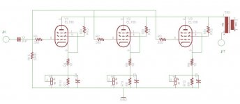
In any biasing scheme, each of the parallel OP tubes need be biased separately.
With cathode self-bias, I'll need 3 electrolytic caps to shunt each of the 3 cathode resistors. Those electrolytic caps I prefer to avoid, if possible.
With fixed bias, should there be only 1 cap feeding from the driver stage, the 3 grids will be DC connected, no matter what I'll do, thus it will be impossible to set individual bias to each OP tube.
Actually I'm left with 2 biasing options. Schematics for those options are attached below.
Clipping assymmetrically between the bottom and top of the waveform. This depends on your limit of bias current to correct the output tube of course. This will also affect your distortion at higher levels - try to download and play a 1kHz tone through it into an 8ohm load and check on a scope what happens at higher levels. You never know, the driver operating point may be 50V off and causing all the trouble.
I'll check the operating condition of the amp. May be trimming the bias will improve the situation.
Attachments

Ok - I think I'd use the first schematic, so as to avoid cathode capacitors.
For the biasing, I'd only have one capacitor for the bias circuit, not for each pot. For each pot however I'd put a bleed resistor down from the pot centre to ground, so any pot noise cut the tube off instead of leaving it floating.
As you are driving 3 tubes now, I'd also go for a meaty driver like a 6n6p or something..
get another amp just like the one you have and bridge each. linked amp page seems to indicate that the secondaries are floating or otherwise allow it. fwiw.
Yes, I know about that option and considered it. In this amp, "bridging" means connecting the 2 inputs and outputs in parallel. I'll have to test it and see if it eliminates distortion altogether with the 1 amp I have.
Actually bridging means connecting the inputs in parallel, and connecting the outputs in a bridge configuration where the speaker is connected between the two transformers (series connected). This requires that the transformers are floating, and can be connected such that one amp is inverting with respect to the other amp. It also is best configured with each amp transformer tap value one half of the speaker impedance value.
Actually bridging means connecting the inputs in parallel, and connecting the outputs in a bridge configuration where the speaker is connected between the two transformers (series connected). This requires that the transformers are floating, and can be connected such that one amp is inverting with respect to the other amp. It also is best configured with each amp transformer tap value one half of the speaker impedance value.
Doesn't that turn it into a pushpull?
Yes, it does.
That is what Bridge Topology does.
This is why it gets greater than 2X power out. Each amp is still delivering the same peak voltage to the load. The voltage seen by the load is theoretically 2X and power is thus 4X. In reality about 90% of that is achieved, and it needs matched amps to achieve low distortion.
Last edited:
get another amp just like the one you have and bridge each. linked amp page seems to indicate that the secondaries are floating or otherwise allow it. fwiw.
I tried both channels "bridged" driving 1 speaker. The distortion improved, but not enough. So it seems that my initial hunch about the need of 3 tubes per channel is probably correct. So, I'm probably going to build this amp.
There is one thing I'm going to do before final decision – I'll try to modify the working point of all stages of my existing amp and see then if 2 channels driving 1 speaker will be good enough.
Yes, it does.
That is what Bridge Topology does.
This is why it gets greater than 2X power out. Each amp is still delivering the same peak voltage to the load. The voltage seen by the load is theoretically 2X and power is thus 4X. In reality about 90% of that is achieved, and it needs matched amps to achieve low distortion.
I prefer the sound of SET amps. Should I want PP, I'd go that road initially.
- Status
- This old topic is closed. If you want to reopen this topic, contact a moderator using the "Report Post" button.
- Home
- Amplifiers
- Tubes / Valves
- Medium power SET with parallel OP tubes