Back in the day was 50 years ago. We have new and better tools now, which is great. Note I am not saying those ones are wrong, just that in discussions on here enough questions have been posed to make me think they might need recalibrating.I’ve never heard anyone question the old CBS or JVC test records. They set the standard back in the day.
effective tip mass and LF resonance are real. Effective tip mass is real, even though it's inferred rather than measured. But is vinyl compliance real? All the analyses I have seen assume a rigid cantiliever and assume hooke's law holds for a non-static case. A totally rigid cantilever doesn't make sense to me personally so I prefer to consider a world where there is cantilever flex and it's a transmission line. But willing to be persuaded that I am wrong.Vinyl compliance - effective tip mass HF resonance is as real as tone arm eff. mass - cartridge compliance LF resonance.
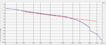
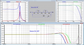
Back onto MMs and I would like to present another rare oddity. The Denon DL-107 which is a wonder from the 70s. Supposedly designed for the same radio turntables the DL-103 MC went into so a low compliance brute of a cartridge. I can't help collecting things like this. Note we are trying the same loading with all cartridges at the moment to test a theory, so optimisation might follow. In this case the simulation and measurement are slightly apart being 3.6dB different between 20kHz and 30kHz. This will need revisiting but again no evidence of mechanical help in the HF region.
Attachments
Shure did some work on non-rigid cantilevers.
https://www.aes.org/e-lib/browse.cfm?elib=3228
Some non-rigid cantilever modeling is also done here.
http://www.pspatialaudio.com/analogy.htm
https://www.aes.org/e-lib/browse.cfm?elib=3228
Some non-rigid cantilever modeling is also done here.
http://www.pspatialaudio.com/analogy.htm
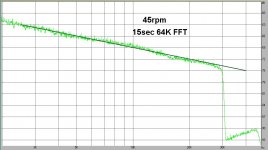
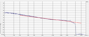
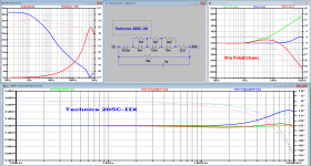
And finally tonight a cartridge people may at least have heard of, the technics snappily named EPC205C-IIL. It's younger brothers the mk3 and mk4 are famed as some of the greatest MM ever made but IMO this one is no slouch. Plus I can't afford the more fabled brethren. The L model has a very low inductance coil which should make it less sensitive to capacitive loading, so lets see how it did. For a cartridge older than my wife ") it did pretty well. Second picture here shows deviation from the simulation and this is around 0.3dB at 20kHz.
it did pretty well. Second picture here shows deviation from the simulation and this is around 0.3dB at 20kHz.
None of this is AES grade data but really not seeing anything to even hint at a mechanical resonance. Now of course I'm not expecting to find anything so I may be blinkered, but data is there for you.
it did pretty well. Second picture here shows deviation from the simulation and this is around 0.3dB at 20kHz. None of this is AES grade data but really not seeing anything to even hint at a mechanical resonance. Now of course I'm not expecting to find anything so I may be blinkered, but data is there for you.
Attachments
Yes those shure papers are very interesting, not least because in later papers they fell into line with the rigid cantilever model. It's very strange, but any mention of velocity in materials and you know that the manufacturer may be thinking of cantilever flex. It's a shame that a lot of this was considered trade secrets and not written down so we are scratching at stuff that was known and then taken to the grave.Shure did some work on non-rigid cantilevers.
https://www.aes.org/e-lib/browse.cfm?elib=3228
And finally tonight a cartridge people may at least have heard of, the technics snappily named EPC205C-IIL. It's younger brothers the mk3 and mk4 are famed as some of the greatest MM ever made but IMO this one is no slouch. Plus I can't afford the more fabled brethren. The L model has a very low inductance coil which should make it less sensitive to capacitive loading, so lets see how it did. For a cartridge older than my wife
What stylus and loading was that test with ?
I have both a mk2 and Umk3 with OEM mk3 stylus and Jico SAS/B and I can vouch for the wonderfully detailed sound of this cart.
really not seeing anything to even hint at a mechanical resonance. Now of course I'm not expecting to find anything so I may be blinkered, but data is there for you.
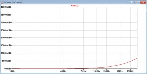
How about that 1 dB...3 dB peak at 24 kHz? It could be a resonance with Q > 1/2 sqrt(2), although the roll-off above it looks to gradual at first sight. At least it's a peak that the MC cartridge hasn't.
I would expect the biggest mechanical peaks for cartridges with a high inductance, high recommended load capacitance and nonetheless a reasonable frequency response.
I've come late to this thread and discovered that it's unfeasible to read all the posts, so I hope you'll forgive me if I mention something that may have been covered...
Even one of the latest posts still treats the cartridge electrical circuit as a simple inductor having series resistance. This simply isn't true and leads to incorrect assumptions about the mechanical system. If you make a multi-frequency electrical impedance measurement of a moving magnet cartridge, you find that hysteresis losses in the pole pieces/core require splitting the inductance in two, with one inductor having parallel resistance. The effect is that at high frequencies, apparent inductance is much lower than low frequency inductance - which makes a big difference to the LC resonance. That same model is also needed for a moving coil cartridge because of transformer coupling to the adjacent magnet (just like loudspeakers). Without a valid electrical model, attempting to deduce a good mechanical model will be hard.
Tinkering just with the electrical model for cartridges designed after 1980 (all I have), simulation says that reduced loading capacitance (200pF maximum) is always a good thing, but that loading resistance usually needs to be increased. I decided that "optimum" loading was one that didn't have a 6-7kHz depression, and tweaking for that invariably causes an HF peak (which I probably won't hear). Now, the interesting thing is that I see that Paul Miller's measured response of an Ortofon 2M showed a very similar response from a test record. Which says that it was only the very early designs that needed the resonant LC equaliser to correct their response and that loading capacitance now forms an unwanted low-pass filter, just as suggested by Cordell.
Sorry I completely forgot to add the cartridge models, they are anything but simple. Agreed that excess capacitance is usually the thing, but right now we are not looking at optimal loading rather seeing if MM response can be explained entirely by electrical means, which so far we have.
@MarcelvdG there is 'something' on one channel at 24kHz but not on the other, so I suspect something else there. Above 20kHz we don't have a test method we can use for that. Needs more thought.
@warrjon Jico SAS stylus same loading as for the other tests 48.5k||192pF.
@MarcelvdG there is 'something' on one channel at 24kHz but not on the other, so I suspect something else there. Above 20kHz we don't have a test method we can use for that. Needs more thought.
@warrjon Jico SAS stylus same loading as for the other tests 48.5k||192pF.
Attachments
Forgot to mention, based on the generator models Hans developed some cartridges (ortofons and modern ATs) do lend themselves to the Cordell 'damped RIAA' approach. Others do not as this leads to a rising response that needs another pole to correct. But some of us are happy to have phono stages that are effectively customised for one cartridge...Which says that it was only the very early designs that needed the resonant LC equaliser to correct their response and that loading capacitance now forms an unwanted low-pass filter, just as suggested by Cordell.
And why not? But my impedance measurements varied significantly between channels (no huge surprise there), so you'd need to measure each channel. I can see I will have to try playing pink noise to see what an FFT of that looks like.... effectively customised for one cartridge...
https://www.aes.org/e-lib/browse.cfm?elib=3228
I undusted the Shure paper and read through it again. Let me post a couple of tidbits that caught my eye. I can’t quote directly because AES has rather strict copyright enforcement so I’ll post them as ‘my understanding’ of what was printed.
They mention that there are cartridges whose design generates voltage from the rotation of the magnet, implying that it’s not always a simple to-and-fro of the magnet as if it were a see-saw that generates the signal. This suggests that pole piece design is not as simple as it looks. For their model at resonance, the bearing point of the cantilever/magnet in the elastomer shifts position in a direction more-or-less perpendicular to the axis of the cantilever. At almost double the resonant frequency, the magnet rotation is ~180 degrees out of phase with the stylus. These two cases were at 19.5kHz and 35 KHz. While these effects were happening above audible frequencies, I’m wondering if the cantilever bearing shifting about and the magnet rotation phase shifting at high frequencies might not be causing some negative effects that fold back down into the audible range, and how to measure for this?
Getting back to pole piece design, my B&O MMC6000 had a MI element that was perpendicular to the cantilever, acted on 4 poles/coils in a push-pull arrangement, and was mounted on the cantilever ahead of the elastomer bearing. I believe some Grado cartridges use a similar 4 pole design. AT employs a dual ‘vee’ magnet arrangement at the elastomer pivot, again, no see-saw. Better, worse? I don’t know, but I loved the B&O and I have an AT150MLX waiting in the wings.
Off topic, but maybe related. The Decca cartridges have coil arranged to sense stylus movement directly. I had one myself a long time ago, and it had an ‘x’ factor that I liked. If you sense stylus motion at the tip like a Decca or as in a MC like a Neumann DST-62, do mechanical resonances in the cantilever behind the stylus matter less?
Hi Ray,
As you well know the cantilever flaps all over the place and it's a miracle the darned thing works as well as it does. I do have a B&O MMC but that's in california. I also have an At150 which I need to ship to norway for measurement. As I am on record saying, the transmission line model for a cantilever makes more sense to me and there are some tantalising glimpses of this in some of the 80s cartridge literature but I'm not sure of the right way to meaure it. For your delectation I have added a diagram of the internals of the DL-109. It's bonkers, so I had to have one. The logic behind it is explained in the patent for it's older brother the DL-107 which I have if you are interested. But 4 pole is more common (think ortofon).
The Decca/Neumann designs (which I think of as sum and difference sensing) do have a simplicity about the setup that is intriguing, as does dynavector. I've never had the pleasure.
Attachments
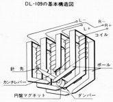
Bill,The logic behind it is explained in the patent for it's older brother the DL-107 which I have if you are interested.
Yes, very much interested!
I actually collect audio patents and would like to study that coil configuration.
Please PM me with a copy.
Ray K
Patents are public. All you need is the number (maybe the country). The USPO site 'can' show it to you, on a good day, if it feels like it. Google Patents is often swifter and better.I actually collect audio patents ..snip.. Please PM me with a copy.
- Home
- Source & Line
- Analogue Source
- mechanical resonance in MMs