I did note in my edit that I worked out the impedance. Did that not show? 356mH and 530Ohms.
Hans: I was talking about serial strapped super OM so 2kOhm and 1160mH. This is a config LD already uses.
BTW any good reason OPA-1632 wouldn't work as the front end?
So may I conclude:
Cart 1) 356mH and 530 Ohm
Cart 2) 580mH and 1KOhm
Cart 3) 1160mH and 2 KOhm
Is there any reason why you should prefer the OPA1632 over the OPA1642 ?
I suspect that current noise is too high for this application, but once I have all 3 Cart values confirmed, I will also show you the S/N for the OPA1632.
And as a matter of fact, I will do these simulations only once.
Hans
IIRC along the lines of these style arrangements
Thanks Scott. I hope Ricardo will write a few words.
but in the end device physics rules the day.
I am about to use TL082 as IC1 and Ne5532 as IC2 for the single ended Aurak V3.
Any strong objections (except the usual mild “you miserable @#$%^&*!”) ?
And as a matter of fact, I will do these simulations only once.
Hans, don’t worry. Bill is a good guy, he won’t take advantage of you.
")
George
Sorry I didn't think anyone was going to go as far as simulating with the device yet! I was just floating it before doing some more research. The only reason for mentioning the 1632 was this http://twistedpearaudio.com/docs/linestages/retro_loz_schematic.pdf. I had remembered that Russ White had done a transimpedance balanced MC stage, which warrants some further investigation because
1) PCBs are available for £26 a pair
2) he does offer them with the nasty SM bits already glommed down for those who can't solder teeny stuff.
So my plan was to mimble off down this particular rabbit hole and see if this board could be re purposed for our needs without any track cutting, in which case there would be a low resistance path to more people trying this out at low risk. But that was as far as I had gotten and no detailed examination of the parametrics. That was the plan for tonight at least until my preamp died. Joy...
Thank you Ricardo. (may I ask you for any reference to the preamplifier you designed which Scott mentions in post #226? )
IIRC along the lines of these style arrangements, which have an absolute limit of re/4 for noise floor. So for .28nV (~5 Ohms noise floor) I can't see running it at less than 1mA for no rbb at all. These circuits are clever reuse of current to effect paralleling of devices but in the end device physics rules the day.
http://www.lcaudio.com/index.php?page=8[/url
Yes. Stole the idea from Leach in late 70s. But I improved noise & THD by more than 10dB, so I think I'm entitled to claim I understood it better than he did.
My latest thoughts are in my Yahoo MicBuilder's Files under ricardo. You have to join.
I used a C cell. Today, I'd almost certainly try LCaudio's photocells.
Anyone used these? There's not a lot of info on the SFH206k datasheet. Maybe use a Photovoltaic cell from a solar panel and drive it with LEDs. We could have a field day claiming Green LEDs gave extra clarity & definition
Shut up Lee! Just Shut UP!!Just buy these from Ye Olde Unobtainium ShoppeEvery few years we had a customer that wanted an op-amp that had 1nV noise but a total Iq of 100uA.
Bill,Sorry I didn't think anyone was going to go as far as simulating with the device yet! I was just floating it before doing some more research. The only reason for mentioning the 1632 was this http://twistedpearaudio.com/docs/linestages/retro_loz_schematic.pdf. I had remembered that Russ White had done a transimpedance balanced MC stage, which warrants some further investigation because
1) PCBs are available for £26 a pair
2) he does offer them with the nasty SM bits already glommed down for those who can't solder teeny stuff.
So my plan was to mimble off down this particular rabbit hole and see if this board could be re purposed for our needs without any track cutting, in which case there would be a low resistance path to more people trying this out at low risk. But that was as far as I had gotten and no detailed examination of the parametrics. That was the plan for tonight at least until my preamp died. Joy...
May be I may give some comment on Russ White's circuit diagram.
It mentions that is meant to be used for a MC Cart.
Gain is 50dB, which is very low for an MC Cart, should be at least 60dB.
But it has two 100 Ohm resistors in series with the cart, producing 2nV/rtHz, which is killing the 1.3nV/rtHz that the OPA1632 is producing.
So these two resistors should be reduced to zero ohm.
With the cart connected in that way, you have a real virtual input circuit, although delpending on your Cart, gain might be a bit high now, but that can be corrected by reducing R1,R3.
One other minor point is that R22,R23 and C11 are playing no role at all and can be omitted.
The full Riaa curve is implemented in this circuit, so your DSP has no corrections to do.
When however you would prefer to involve your DSP, then you can pick the signals Vout+ and Vout- from IC2.
Hans
Hi Hans,
Sorry was not making myself clear, I should have delayed my last mail. I was not intending to use that board exactly as designed. It is a transimpedance stage that is laid out for the 1632 differential amplifier.
Some of us would like to build the balance Aurak circuit following your optimisations, but SOIC opamps don't go onto vero board easily. So I wondered aloud if the twisted pair board might be something that, with a few changes to components could be used to quickly build up the balanced transimpedance MM stage. Board are cheap and always in stock so no group buy worries etc and sure if I asked Russ nicely he could do a special kit for those who cannot solder SM.
But just an idle thought as not sure if that 1632 was good enough. LD thinks yes, you think no
Bill
P.S. Russ did admit that the input series R could be omitted.
TL082 GBW is actually a bit skinny for U1.........I am about to use TL082 as IC1 and Ne5532 as IC2 for the single ended Aurak V3.
Any strong objections (except the usual mild “you miserable @#$%^&*!”) ?
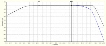
Here's a simulation of TL082 versus AD745 for U1. Single ended Aurak 3, with NE5532 as U2. Both plots with C14 2pf (strays only) and C13 100pf (hf roll-off control). TL082 blue, AD745 black.
LD
Attachments
Last edited:
Bill,Hi Hans,
Sorry was not making myself clear, I should have delayed my last mail. I was not intending to use that board exactly as designed. It is a transimpedance stage that is laid out for the 1632 differential amplifier.
Some of us would like to build the balance Aurak circuit following your optimisations, but SOIC opamps don't go onto vero board easily. So I wondered aloud if the twisted pair board might be something that, with a few changes to components could be used to quickly build up the balanced transimpedance MM stage. Board are cheap and always in stock so no group buy worries etc and sure if I asked Russ nicely he could do a special kit for those who cannot solder SM.
But just an idle thought as not sure if that 1632 was good enough. LD thinks yes, you think no
Bill
P.S. Russ did admit that the input series R could be omitted.
Now that I know what you have in mind, I will look again at this design, but now modified into an Aurak setup. The noise measurement will show in howfar the opa1632 is o.k. for the job.
Hans
Whilst I really like and applaud the balanced Aurak design, actually most of the benefit I see arising from the fact of transimpedance loading, rather than being balanced. Indeed, low input impedance can greatly help environmental sourced interface noise per se, virtually eliminate it perhaps, even for single ended preamp topology.
Also, eliminating LCR MM/MI loading resonant effects is common to both balanced and single ended designs. As is any sonic effect on the generator, I think.
My point is that it doesn't have to be balanced to realise most of the gain here('scuse pun!). But that said I do always enjoy and appreciate the elegance of things balanced.
LD
well I have balanced input power amps, balance I/O on miniDSP so for me balanced phono is a logical progression.
Of course being pedantic its the identical series resistors that make it balanced. Balanced does not have to be differential and many differential inputs are not balanced
Hans: Sorry again about the confusion.
Of course being pedantic its the identical series resistors that make it balanced. Balanced does not have to be differential and many differential inputs are not balanced
Hans: Sorry again about the confusion.
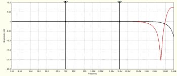
Here's a swift simulation of OPA1642 (Red) versus OPA1632 (black) in the front end of balanced version of Aurak 3.
The effect around 300kHz et seq is due to GBW limitations in the 1642, so if one is going to allow the circuit to operate at such bandwidth, this might be sensible to intentionally roll-off before then for the OPA1642, I think, for stability.
LD
The effect around 300kHz et seq is due to GBW limitations in the 1642, so if one is going to allow the circuit to operate at such bandwidth, this might be sensible to intentionally roll-off before then for the OPA1642, I think, for stability.
LD
Attachments
Here's a swift simulation of OPA1642 (Red) versus OPA1632 (black) in the front end of balanced version of Aurak 3.
The effect around 300kHz et seq is due to GBW limitations in the 1642, so if one is going to allow the circuit to operate at such bandwidth, this might be sensible to intentionally roll-off before then for the OPA1642, I think, for stability.
LD
LD, can you please show the circuit diagram that you used for this simulation, because none of my sims does show anything like this.
Hans
well I have balanced input power amps, balance I/O on miniDSP so for me balanced phono is a logical progression.
Of course being pedantic its the identical series resistors that make it balanced. Balanced does not have to be differential and many differential inputs are not balanced
Hans: Sorry again about the confusion.
Hi Bill,
I simulated the OPA1632 circuit for which you can get a PCB, and yes it turns out that this OPA can be used very well.
Measured noise was 79.9 dBA, even one dB better as with the OPA1642.
See the modified circuit into an Aurak design below.
Hans

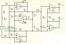
Hi Hans, here's the simulation schematic. What GBW value is in your model for the 1642 ?LD, can you please show the circuit diagram that you used for this simulation, because none of my sims does show anything like this.
Hans
PS included are 0.22pf estimates of miller C due to strays.
LD
Attachments
LD, can you please show the circuit diagram that you used for this simulation, because none of my sims does show anything like this.
Hans
LD
Phase margin of the OPA1642 at 0dB gain is 67,5 degrees. In my simulations I used a worse phase margin of 45 degrees to stay on the safe side. So the question is, what model did you use for your simulation.
Hans
TI's spice model dated Oct 2011.So the question is, what model did you use for your simulation.
LD
TI's spice model dated Oct 2011.
LD
Then again, can you show the circuit diagram that you used, there must be something that causes this effect.
And what Sim program do you use, LTSpice ?
Hans
Great, yes thanks all ! I think you're going to like this..........Hans, thank you so much. I will order up a couple of sets of boards and try and get some built up for testing so we have a set to post around to different people.
It's moot as to GBW when a 1632 is used. Presumably the layout is already field proven too, which bodes well methinks.
LD
Last edited:
Hans, thank you so much. I will order up a couple of sets of boards and try and get some built up for testing so we have a set to post around to different people.
As you may have seen, I had used 2* 250 Ohm resistors in the input instead of 2* 350 Ohm, to fulfil 2*L-R for 580 mH and 460 Ohm.
Here is the corrected diagram. Noise is still the same.
Hans

- Home
- Source & Line
- Analogue Source
- mechanical resonance in MMs