You can make the comparison to a Cathodyne Phase Inverter ...
You mean that phase splitter circuit with 50% feedback?
Gain is the ratio of input to output. A cathodyne has a single ended input and differential output. The differential output is twice the magnitude of the input. The Cathodyne has a gain of two.
That 12HL7 triode pic was at 50V/div horiz., and 20 mA/div Vert.
350 V peak is the practical limit for the curve tracer lately. It's got a 1500V max scale too, but the last time I used that, it arc'd over in the DUT selector switch. Too much work to fix the switch every time. The 12HL7 is rated for 400V plate voltage. And 330V screen voltage. Should work OK for a triode at 400V. (they are only $1 each)
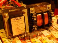
I have almost all the parts to build a Circlotron on the shelf here. The floating B+ supplies can be done cheaply with some Stancor TGC175-230 industrial xfmrs (or the many equivalents around). These have dual 115V primaries and dual 115V secondaries. Those are placed on a split bobbin, with only 69 pf capacitance between primaries and secondaries. (low C is important) 175 Watt each. I don't have a 600 Ohm OT however, but I have some large toroid cores and some moderate C cores that could be wound up.
I'm more likely to just use the Elliptical Twin circuit with an Edcor OT though, less % CFB. (28% CFB using 40% UL taps: .4/(1+.4))
If one uses the driver tubes in pentode mode, then bootstrapping can (effectively) eliminate the output stage CFB altogether.
Don't really need the CFB with the Crazy Drive outputs and some local feedbacks (from the output cathodes) to the driver cathodes.
350 V peak is the practical limit for the curve tracer lately. It's got a 1500V max scale too, but the last time I used that, it arc'd over in the DUT selector switch. Too much work to fix the switch every time. The 12HL7 is rated for 400V plate voltage. And 330V screen voltage. Should work OK for a triode at 400V. (they are only $1 each)
I have almost all the parts to build a Circlotron on the shelf here. The floating B+ supplies can be done cheaply with some Stancor TGC175-230 industrial xfmrs (or the many equivalents around). These have dual 115V primaries and dual 115V secondaries. Those are placed on a split bobbin, with only 69 pf capacitance between primaries and secondaries. (low C is important) 175 Watt each. I don't have a 600 Ohm OT however, but I have some large toroid cores and some moderate C cores that could be wound up.
I'm more likely to just use the Elliptical Twin circuit with an Edcor OT though, less % CFB. (28% CFB using 40% UL taps: .4/(1+.4))
If one uses the driver tubes in pentode mode, then bootstrapping can (effectively) eliminate the output stage CFB altogether.
Don't really need the CFB with the Crazy Drive outputs and some local feedbacks (from the output cathodes) to the driver cathodes.
Attachments
Last edited:
"The Lockhart transformer diagram seems lacking in # of interleaves,"
Did McIntosh use it ? Reading the patent papers don't think they did. Money saving.
Well here is a picture of the hardware i found the latest years")
C cores with a total center leg of 20cm2, not as big as they should be (hope is that they can deliver about 58w). EI 130 laminate for the power supply.

best regards Kim
Did McIntosh use it ? Reading the patent papers don't think they did. Money saving.
Well here is a picture of the hardware i found the latest years
C cores with a total center leg of 20cm2, not as big as they should be (hope is that they can deliver about 58w). EI 130 laminate for the power supply.
best regards Kim
`Are you referring to the input to output stage of the whole am?
I was referring to just the output stage and there is absolutely no measurable voltage gain in the 6550 output stage of the Mc275 or Mc60..You can measure this plain as day on an RMS voltmeter and Doc Hoyer knows the circuit better than anyone and he knew the designer as well.
You mean that phase splitter circuit with 50% feedback?
Gain is the ratio of input to output. A cathodyne has a single ended input and differential output. The differential output is twice the magnitude of the input. The Cathodyne has a gain of two.
I was referring to just the output stage and there is absolutely no measurable voltage gain in the 6550 output stage of the Mc275 or Mc60..You can measure this plain as day on an RMS voltmeter and Doc Hoyer knows the circuit better than anyone and he knew the designer as well.
The only you can prove this to yourself is to measure it.
The circuit is very unconventional and there are probably 3 people in the country that understands the inner mechanics of that transformer and circuit. we already audio signal on the cathodes and the screens and the plates and G1 of the 6550s before we even plug in the tube..Measure the RMS at G1 with reference to ground and then at the plate with reference to ground and you will see a loss,not a gain there.
You mean that phase splitter circuit with 50% feedback?
Gain is the ratio of input to output. A cathodyne has a single ended input and differential output. The differential output is twice the magnitude of the input. The Cathodyne has a gain of two.
The circuit is very unconventional and there are probably 3 people in the country that understands the inner mechanics of that transformer and circuit. we already audio signal on the cathodes and the screens and the plates and G1 of the 6550s before we even plug in the tube..Measure the RMS at G1 with reference to ground and then at the plate with reference to ground and you will see a loss,not a gain there.
Last edited:
Measure the RMS at G1 with reference to ground and then at the plate with reference to ground and you will see a loss,not a gain there.
The voltage measurements should really be done with respective to the cathode - not ground, especially in the the case of the Mac... Deja vu? Anyway, the gain of the output stage is between 1.5~1.8 depending on the output tube type.
The voltage measurements should really be done with respective to the cathode - not ground, especially in the the case of the Mac... Deja vu? Anyway, the gain of the output stage is between 1.5~1.8 depending on the output tube type.
mac1949.pdf

Powersupply is an ac short so the tube will see the two windings as one ?
Best regards
The voltage measurements should really be done with respective to the cathode - not ground, especially in the the case of the Mac... Deja vu? Anyway, the gain of the output stage is between 1.5~1.8 depending on the output tube type.
You are correct in that conventional amps have to be measured from the cathode however in the case of the Mac circuit you can't do this because the part of the signal voltage is already on the mac's cathodes even with the kt8s not installed and it simply swings the voltage from the cathodes and G1..If you talk to Doc Hoyer he will explain this as well but also the Mac trafo has 3 separate impedances all coming out to about 600 ohms each so again,conventional wisdom does not apply with this circuit.Doc Hoyer knew Frank McIntosh and Sidney Corderman and this is why they trusted with the designs and the way circuit operates..It's very tightly guarded and he has the only one that has actual winding blueprints for the Opt trafos so I think he knows what he's talking about.
Think about how you can take the output tubes out of a Mac and it still plays with amazing clarity but with reduced power and bass..Try that with a conventional amp..
Last edited:
Could you not read the differential voltage between the grid/plate and the cathode with a dual trace scope (with the KT88 installed) or a volt-meter?you can't do this because the part of the signal voltage is already on the mac's cathodes even with the kt8s not installed and it simply swings the voltage from the cathodes and G1.
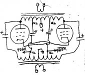
Equivalence of the Mac circuit to the Circlotron circuit (secondary left out for clarity):
Just the B+ battery getting moved. No longer any dangerous B+ across adjacent bifilar wires. OT is at ground DC potential in the Circlotron. Same AC peak current carried in the winding, so wire does not need to be bigger. 1/2 the bobbin area saved. Reduced leakage L and distributed C.
Just the B+ battery getting moved. No longer any dangerous B+ across adjacent bifilar wires. OT is at ground DC potential in the Circlotron. Same AC peak current carried in the winding, so wire does not need to be bigger. 1/2 the bobbin area saved. Reduced leakage L and distributed C.
Attachments
Last edited:
The voltage measurements should really be done with respective to the cathode - not ground, especially in the the case of the Mac... Deja vu? Anyway, the gain of the output stage is between 1.5~1.8 depending on the output tube type.
Agreed. The output voltage swing is the change in Va-k. The fact that the voltage swing is being divided into two coils is unremarkable. The same thing happens in any amp with cathode feedback. The Mac output stage is a 50% CFB amp with a unique circuit arrangement and winding that makes the capacitance between the coils a non-issue.
The correct way to measure output voltage of this circuit is with a differential probe across the anode and cathode of an output device. I have such a probe and would do this measurement if I weren't so convinced that it will reveal exactly what I expect it to.
Gain is just the ratio of output to input. I don't see a good logical justification for only counting the cathode or anode swing by itself as the total output voltage swing.
Last edited:
The circuit is very unconventional and there are probably 3 people in the country that understands the inner mechanics of that transformer and circuit. we already audio signal on the cathodes and the screens and the plates and G1 of the 6550s before we even plug in the tube..Measure the RMS at G1 with reference to ground and then at the plate with reference to ground and you will see a loss,not a gain there.
I will measure it next time I have my amp out, but measure what? If anything this will be a fun way to break in the new high-voltage differential probe I just got. You are only measuring half of the output voltage. The output voltage is the sum of the anode and cathode voltage swings. Both coils are contributing to the output on the secondary. You can't just toss one out in the analysis.
I certainly don't agree that there are only 3 people in the country who understand this circuit. I mean, I've read a paper from an EE senior project (bachelor's degree) where a guy wound a trifilar Mac OT that worked (not the most impressive results I have ever seen but it worked). They aren't that magical.
Last edited:
Which differential probe do you have? I don't have one, so I just resort to using the "Ch A-Ch B" function on the scope.The correct way to measure output voltage of this circuit is with a differential probe across the anode and cathode of an output device. I have such a probe and would do this measurement if I weren't so convinced that it will reveal exactly what I expect it to.
I think this confusion over 2X gain versus "unity" gain is just an artifact of whether one is including the grid to cathode drive voltage swing in the input signal measurement. If the tubes were Mosfets, with high gm, the gain from the grid (gate) would approach 2. With tubes, it looks more like 1 (or more likely 1.5 ~ 1.8 depending on gm) from the grids. Sweep tubes will certainly get one closer to the 2X figure.
Which differential probe do you have? I don't have one, so I just resort to using the "ChA-ChB" function on the scope.
This one here.
That 12HL7 triode pic was at 50V/div horiz., and 20 mA/div Vert.
350 V peak is the practical limit for the curve tracer lately. It's got a 1500V max scale too, but the last time I used that, it arc'd over in the DUT selector switch. Too much work to fix the switch every time. The 12HL7 is rated for 400V plate voltage. And 330V screen voltage. Should work OK for a triode at 400V. (they are only $1 each)
It's hard to find data for tubes out to the voltages that we are going to swing on these things. I have tested CCS-loaded 6SN7, 6BL7, and 841s as 200V+rms drivers. If you are interested I can send you FFTs to compare to the 12HL7.
841 was the best (and I admit to using it mostly for the looks) but the 6BL7 was actually a close second.
A lot of tubes have curves that really start to fall over past 500V, which is what happens in the 6SN7.
I will measure the impedance of the output trafo is what I meant..Notice when you measure a conventional output transformers output imp,you come up with one reading whether it be 6.6k or whatever.With the mac,you measure the windings separate and two will be equal in value and the 3rd is higher..As I recall on the mc60s I measured 600 or 900 on the cathode windings and the same on the plate and the screen was different..The point is,you typically couldn't load a 6550 with that voltage with 600 ohms plate to plate.That is a small fraction of what it typically loads a pair of 6550s so this once gain it proves that it is not being used as a voltage amplifier.I will measure it next time I have my amp out, but measure what? If anything this will be a fun way to break in the new high-voltage differential probe I just got. You are only measuring half of the output voltage. The output voltage is the sum of the anode and cathode voltage swings. Both coils are contributing to the output on the secondary. You can't just toss one out in the analysis.
I certainly don't agree that there are only 3 people in the country who understand this circuit. I mean, I've read a paper from an EE senior project (bachelor's degree) where a guy wound a trifilar Mac OT that worked (not the most impressive results I have ever seen but it worked). They aren't that magical.
Lets say for all practical purpose that tube has a 2 to 1 gain,would you also contend that the tube is amplifying current? The circuit is so unconventional that it throws much assumed theory out the window..
Last edited:
"The circuit is so unconventional that it throws much assumed theory out the window.."
Not really. The two 600 Ohm windings form a 2400 Ohm winding (in series) for the tube. (2X turns gives 4X impedance) Just what the tube wants. There is nothing mystical about the Mac OT. Where one puts the B+ or ground references is immaterial to the AC current. The Mac OT is just a Circlotron that has had its primary windings doubled up, so that a single B+ source can be used for both P-P tubes.
Not really. The two 600 Ohm windings form a 2400 Ohm winding (in series) for the tube. (2X turns gives 4X impedance) Just what the tube wants. There is nothing mystical about the Mac OT. Where one puts the B+ or ground references is immaterial to the AC current. The Mac OT is just a Circlotron that has had its primary windings doubled up, so that a single B+ source can be used for both P-P tubes.
Last edited:
"The circuit is so unconventional that it throws much assumed theory out the window.."
Not really. The two 600 Ohm windings form a 2400 Ohm winding (in series) for the tube. (2X turns gives 4X impedance) Just what the tube wants. There is nothing mystical about the Mac OT. Where one puts the B+ or ground references is immaterial to the AC current. The Mac OT is just a Circlotron that has had its primary windings doubled up, so that a single B+ source can be used for both P-P tubes.
But it also eliminates leakage inductance between the primaries that you typically have with a conventional transformer. Did you guys say there is another guy that can rewind a pair of 225 opt trafos? Doc is getting up in years and I'm worried when he retires or goes to the great beyond that we can't these rewound.
I think this confusion over 2X gain versus "unity" gain is just an artifact of whether one is including the grid to cathode drive voltage swing in the input signal measurement. If the tubes were Mosfets, with high gm, the gain from the grid (gate) would approach 2. With tubes, it looks more like 1 (or more likely 1.5 ~ 1.8 depending on gm) from the grids. Sweep tubes will certainly get one closer to the 2X figure.
I am getting a gain of ~1.7 in my UC amp with KT88s. I have been severely tempted to throw Mosfets in there as the output devices. I'd need to change the polarity of the bias servo, but the increase in swing and elimination of screen current (which works against signal current) are attractive attributes.
I would really love to compare results between my UC amp and your circlotron some day. I didn't end up using any global feedback loop. If you can get a linear enough driver (and low DCRs out of your OT windings) it really isn't necessary.
Did you catch my thread on my take on a high-gm pentode high swing linear driver? I'd love to have your comments on the circuit. I'm about 2/3 done bread-boarding it.
- Status
- This old topic is closed. If you want to reopen this topic, contact a moderator using the "Report Post" button.
- Home
- Amplifiers
- Tubes / Valves
- MC275 OPT manual rewinding