I don't have much experience, but I agree. Whenever I've tried a current mirror on top of the LTP, the sound has been seriously degraded but the THD has been much lower.constructors usually place a current mirrors instead of collector resistors but this ruin the musicality even worse.
Are you willing to share more of your listening observations? How do you find single end vs complementary stages? What improvements cascoding and CFP make for different stages etc. Have you tried JFETs for VAS?
Lazy Cat,
Rather not small enough for the purpose it serves, as it, ideally, should be zero Ohm.which has for the purpose it serves, to small input impedance,
Lazy Cat,
Rather not small enough for the purpose it serves, as it, ideally, should be zero Ohm.
Yeah, and zero current too ... ideally, but in a real world there is real impedance anadequately loading previous stage. As said before there are many solutions to this problem, but which one is more musical ... as that's the only thing it counts for me.

I don't have much experience, but I agree. Whenever I've tried a current mirror on top of the LTP, the sound has been seriously degraded but the THD has been much lower.
Are you willing to share more of your listening observations? How do you find single end vs complementary stages? What improvements cascoding and CFP make for different stages etc. Have you tried JFETs for VAS?
Discrete single ended VAS is filled with double differential stages, current mirrors, folded cascodes ... every possible way (to "suppress" the sound) to bring out symetrical signal, referenced to ground, at its output. Why choosing a lot of electrical tricks to form the signal it can be done much simpler? For me, if it is single ended, it should be until the speaker connection, so fully single ended configuration only.
Symetrical complementary stages have more relaxed, naturaly flown and realistical transient sound than single ended design.
I know that in this forum everything is about the numbers, but sometimes personal listening observations regarding some electrical designs have to be enlightened. I'm sorry if my remarks offend some intelects around here.

I wish more people here reviewed the sound of different topologies and parts more often than they do. It's the sound that matters, "musicality" or "neutrality" or whatever we're after.I know that in this forum everything is about the numbers, but sometimes personal listening observations regarding some electrical designs have to be enlightened. I'm sorry if my remarks offend some intelects around here.
I'm in the phase to collect some good core parts like toroids, big capacitors, etc.
I was thinking to buy RIFA low ESR, low ESI capacitors 22 mF/100V (PEH169PV5220QB2) and ultrafast recovery rectifier double diodes 2 x 60 A/400 V (STTH120R04TV) for the power supply.
Still I have to find some really low noise 1 kVA toroid. Any suggestion?
I was thinking to buy RIFA low ESR, low ESI capacitors 22 mF/100V (PEH169PV5220QB2) and ultrafast recovery rectifier double diodes 2 x 60 A/400 V (STTH120R04TV) for the power supply.
An externally hosted image should be here but it was not working when we last tested it.
An externally hosted image should be here but it was not working when we last tested it.
Still I have to find some really low noise 1 kVA toroid. Any suggestion?
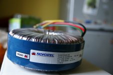
http://en.noratel.ezpublish.no/
When I built my Leach amp I am using transformer from this supplier, mine is smaller - just about 11Kg and diam. 20cm and 800VA. You should ask bigger
they call it - Audio transformer....shielded and silent
But it will not be cheap....
here is picture of mine...
When I built my Leach amp I am using transformer from this supplier, mine is smaller - just about 11Kg and diam. 20cm and 800VA. You should ask bigger
they call it - Audio transformer....shielded and silent
But it will not be cheap....
here is picture of mine...
Attachments
Last edited:
Thanks, it looks very promising. 
I also found something like low noise transformer by Plitron. I have to check more.
I also found something like low noise transformer by Plitron. I have to check more.
An externally hosted image should be here but it was not working when we last tested it.
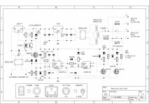
Maximus Soft Start
Lately some experimenting was performed on soft start circuit for Maximus amplifier. I made quite some tests with triac as power switch and phase control soft start but there was just too much power harmonics interferences when triac is completely on. So I returned to good old relay switch to softly turn on massive 2 kVA power supply. I also employed external 12 V trigger signal to turn on amplifier remotely. The result is something like schematics below.
Lately some experimenting was performed on soft start circuit for Maximus amplifier. I made quite some tests with triac as power switch and phase control soft start but there was just too much power harmonics interferences when triac is completely on. So I returned to good old relay switch to softly turn on massive 2 kVA power supply. I also employed external 12 V trigger signal to turn on amplifier remotely. The result is something like schematics below.
Last edited:
harmonics interferences when triac is completely on.
If you are talking about the few commutating volts about the zero crossing here, you can use a relay to short out the TRIAC after the soft-start has finished.
Just pointing out that the TRIAC commutation issue can be dealt with.
I also use a power resistor in one of my designs to limit in-rush current in preference to phase control. I also bolt a normally closed mains voltage/current rated thermal switch on top of the power resistor, to disconnect power before the resistor catches fire in the event of a relay or timing circuit failure.
I also use a power resistor in one of my designs to limit in-rush current in preference to phase control. I also bolt a normally closed mains voltage/current rated thermal switch on top of the power resistor, to disconnect power before the resistor catches fire in the event of a relay or timing circuit failure.
If fixed value resistor is used that's one possible failure event. In your case thermal connection between thermal switch and the power resistor must be very good (fast thermal transfer) and even than there is possibility to burn out resistor. I made some tests with NTC as in-rush current limiter and so far it works fine. In the case of major failure only 10A fuse will die, I hope.
What parts in your design phase of this system limited you to plus and minus 100 volts? Could you have done plus and minus 120 volts to get about 750 watts into 8 ohms? which would have been a 50 percent efficiency based on a roughly 1500 watts available from the wall socket per channel. This could be a design to the max based on that limitation. Just curious, I am not advocating for you to change what you have presented.
There is only one part in present Maximus schematics who's limiting rail voltages to 100 V and that is IRF driver transistor in power stage. I choose this mosfet regarding to its astonishing sound atributes but there are plenty other options for this part if you would like to go to 120 V rail potential. VA stage stays completely the same, only one adaptation has to be performed and that is the value of predriver source feedback resistors.
Also consider a bit higher price for smoothing capacitors in power supply but there is nothing else stoping you to go for 750 Wrms on 8 ohms. You could even say that your amp has one HP (horse power) on 8 ohms.
Also consider a bit higher price for smoothing capacitors in power supply but there is nothing else stoping you to go for 750 Wrms on 8 ohms. You could even say that your amp has one HP (horse power) on 8 ohms.
What I would like to point out considering Maximus soft start schematics is that this circuit is suitable to use with all other DIY amplifiers. Features:
- adaptable soft start time delay
- complete isolation when power switch is turned off
- stand-by/on front panel push button with LED indication
- low power consumption in stand-by mode
- local/remote 12 V external trigger switch for system power control with interference free galvanic isolation
Check out the web for simpler but the same functionality circuit, like to see it.
Last edited:
If fixed value resistor is used that's one possible failure event. In your case thermal connection between thermal switch and the power resistor must be very good (fast thermal transfer) and even than there is possibility to burn out resistor. I made some tests with NTC as in-rush current limiter and so far it works fine. In the case of major failure only 10A fuse will die, I hope.
I use a rather large al-clad wirewound resistor that doesn't burn out before the temp switch operates.

I use a rather large al-clad wirewound resistor that doesn't burn out before the temp switch operates.
Would you suggest me to replace NTC with wirewound Aluminium Clad resistor and attached thermal switch? Anything for safety measures as this power is no joke at all.

Last edited:
- Status
- This old topic is closed. If you want to reopen this topic, contact a moderator using the "Report Post" button.
- Home
- Amplifiers
- Solid State
- "Maximus Power Amp"