Anybody play with these yet?
http://www.maxim-ic.com/quick_view2.cfm/qv_pk/4851/ln/
Or should this post be in Chip Amps?
BTW - it does list a high PSRR
http://www.maxim-ic.com/quick_view2.cfm/qv_pk/4851/ln/
Or should this post be in Chip Amps?
BTW - it does list a high PSRR
It looks like it would be an interesting chip to work with (I don't like the TQFP package it comes in though).
It lists a high PSRR but that's only at 1kHz where that figure just so happens to be at its best (marketing strategy...). At 20kHz the PSRR is closer to -50dB instead of the -90dB at 1kHz. I also hate how everyone markets their stuff as 25/50W when that's at 10% THD+N...
It can be used without an output filter but it would radiate a lot of HF garbage, so it would be best to use a filter if you planned to make an amp based on this chip.
You can peruse spec sheets all day but that won't help you figure out how the thing will actually sound. If you're feeling adventurous take a stab at building one. That's what I'm doing, just with something else")
It lists a high PSRR but that's only at 1kHz where that figure just so happens to be at its best (marketing strategy...). At 20kHz the PSRR is closer to -50dB instead of the -90dB at 1kHz. I also hate how everyone markets their stuff as 25/50W when that's at 10% THD+N...
It can be used without an output filter but it would radiate a lot of HF garbage, so it would be best to use a filter if you planned to make an amp based on this chip.
You can peruse spec sheets all day but that won't help you figure out how the thing will actually sound. If you're feeling adventurous take a stab at building one. That's what I'm doing, just with something else
I have a couple of these with me.
Has anyone used this ic i.e implemented it as an amplifier before?
OR
can someone design the pcb for this ic based on the application circuit in the datasheet pdf(http://pdfserv.maxim-ic.com/en/ds/MAX9709.pdf) .there is a evaluation kit also for this out here>>http://pdfserv.maxim-ic.com/en/ds/MAX9709EVKIT.pdf
the package that i have is THIN QFN, 56 lead.
Sagar
Hi sir,How good is the max9709?
I´m working on the pcb design.

can u provide me the schematics for your design, and can u just tell me how is the MAX9709 working, is it reliable as i'm about to design an amplifier out of those, so please provide me the data.
Thank you
Cheers,
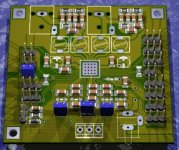
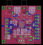
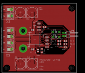
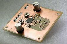
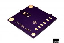
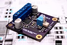
i build myself a 9709 monostage in 1-layer-design. So far temperature is not a problem, but i havent tried a 100%-run on 22V.
Powered by 12V PSU the IC topside will be at ~42°C after 10 minutes of 1kHz square wave input near clipping, so at 12V supply voltage, no additional heatsinking is required.
Strangely the IC is only pulling some 800mA from the PSU at this, so i gues impedance of the speaker is not as low as 4ohms.
Layout is working as is and it is considered to place a heatsink on the bottom side of the pcb.
Working params are:
SSM 200kHz +/-4
Mono bridged (1x50W)
22V max input
36dB gain
120°C temp shutdown via /mute input
filterless output
Cheers doc
Attachments
Last edited:
Hi,
haven't got a notification for your reply, so sorry for the delayed answer.
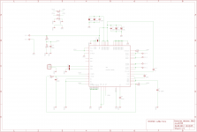
As you can see, /SHDN and /MUTE are low-active, so, to enable the chip (/SHDN) and unmute it (/MUTE) both needs to be on high-level. Thats why /SHDN is connected to the 10k/10k Divider R6/R7 forming a high-level from VDD.
/MUTE is connected in that way, that the chip gets muted whenever the thermal-protection trips. R1 & C5 is forming a time-constant to filter this signal and mute ringing from the set thermal-trip-point. As from the datasheet you'll see, that /TEMP is open drain and needs to be connected to either REG (internal 6V regulator output) or high-level. So why did i connected this to HIGH rather than REG is, that the REG-output is not active in /SHDN mode and you may get in trouble while power-up-sequence. I had problems with this behavior when using the MAX9704 chip.
In normal operation, /TEMP is internally on high-level and the pin is "open drain output". So /MUTE is somewhat "high" as well. When thermal-protection is kicking in, this pin goes low and mutes the device. When the temp gets down, the chip is unmuted again.
Have a look into the dev-kit datasheet here:
MAX9709EVKIT Evaluation Kit for the MAX9709 - Overview
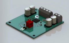
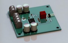
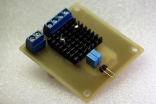
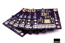
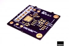
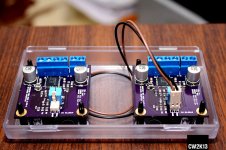
I made some PCBs now running here. 2x50W Mono.
haven't got a notification for your reply, so sorry for the delayed answer.
As you can see, /SHDN and /MUTE are low-active, so, to enable the chip (/SHDN) and unmute it (/MUTE) both needs to be on high-level. Thats why /SHDN is connected to the 10k/10k Divider R6/R7 forming a high-level from VDD.
/MUTE is connected in that way, that the chip gets muted whenever the thermal-protection trips. R1 & C5 is forming a time-constant to filter this signal and mute ringing from the set thermal-trip-point. As from the datasheet you'll see, that /TEMP is open drain and needs to be connected to either REG (internal 6V regulator output) or high-level. So why did i connected this to HIGH rather than REG is, that the REG-output is not active in /SHDN mode and you may get in trouble while power-up-sequence. I had problems with this behavior when using the MAX9704 chip.
In normal operation, /TEMP is internally on high-level and the pin is "open drain output". So /MUTE is somewhat "high" as well. When thermal-protection is kicking in, this pin goes low and mutes the device. When the temp gets down, the chip is unmuted again.
Have a look into the dev-kit datasheet here:
MAX9709EVKIT Evaluation Kit for the MAX9709 - Overview
I made some PCBs now running here.
2x50W Mono.Attachments
Last edited:
TY doctormord you are a genius.
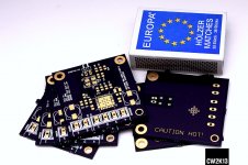
+1 to that! Very impressive amp the size of a matchbox. Why people still want to play around with a 70 lb class A home heater amp I don't know. The future is here.
....Why people still want to play around with a 70 lb class A home heater amp I don't know. The future is here.
I agree. I guess there are a lot of purists that do! There are a lot of very nice sounding class D amps to build, or buy commercially.
The transition and rise of Class-D is similar to what happened with analog vinyl records to CD's. Essentially, the CD player has a small low power DAC that makes line-level signals from digital music data. The Class-D amp is essentially taking that line-level DAC (typically drives a 10 kOhm load up to a few volts) and made it speaker-level DAC, or as a ADC-to-DAC since we are still feeding it RCA line-level inputs. Some Class-D's have optical or USB digital input and you would think they can skip the ADC but in reality, I think there is still an internal line level ADC to line levels which are then fed to amp. If people are happy with the signal that their CD player produces at line-level, there is no reason why they should not be happy with the same concept applied to a 8 ohm load driven to say 24 volts. I suppose there are still people who insist in the "lossless" analog signal from a vinyl record or reel-to-reel... Then there are folks who still insist on tubes... that is another story. Although I hear the new TPA31xx's from TI are as good or better than some tube amps.
Why should there be an internal ADC?. Some amps do and some amps don't. The Sinewave amps do have ADC internally, but many T.I. based amps like Lyngdorf (developed by Lyngdorf and sold to T.I.), Sumoh and panasonic don't.
I have a MiniAMP from MiniDSP that creates the PWM signal fed to the poweramp from an I2S input or spdif.
I have a MiniAMP from MiniDSP that creates the PWM signal fed to the poweramp from an I2S input or spdif.
- Status
- This old topic is closed. If you want to reopen this topic, contact a moderator using the "Report Post" button.
- Home
- Amplifiers
- Class D
- max9709