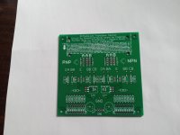
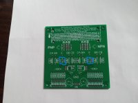
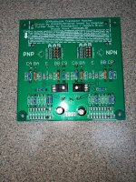
It's a very simple circuit. The critical parts are 4 x 100R0, 0.1% resistors and I used 4 x 10K0, 0.1% resistors. Either 1/2 watt or 0.6 watt resistors should do fine. Use good sockets and switches from authorized vendors. Cheap ones don't work well at all - I tried. The LEDs are 3mm normal efficiency red LEDs, they fit in the holes of the TO-126 transistors. Beyond that, components you find listed are approximate. The current select resistors will vary between NPN and PNP CCS transistors (on the emitters and through the switches). Then you have the resistors that set current through the LEDs, those values will be fine, you could probably vary them a little without any ill effects.
You only need a couple capacitors from each supply to ground. The others are not required.
You only need a couple capacitors from each supply to ground. The others are not required.
hi,Do you by chance also have the BOM that would accompany the boards? If so, I will hit you up on PM and get one from you. Thank you so very much.
BOM was attached to this post
https://www.diyaudio.com/community/...ors-measuring-the-results.307138/post-7032373
Sockets:
I have used ED9164-08-ND, ED7064-ND and ED7636-ND. For larger leads I use a larger, square section hole with fork type contacts. Sorry I don't have that part number handy. Those are Digikey numbers.
8-DIP: i've ordered something like this: 5435802-9 or NDPL08V
Hello everyone,
I purchased pcb's from Rick Ray (see pic) and I am ready to process my BOM. I would like to ask a few rookie questions:
1. Do the 4 jumpers labeled Base Short need to be populated ?
2. I am planning to leave the capacitors by the 0.1% (100R and 10K) resistors unpopulated. Correct ?
3. Could either of these caps be used for C1 and C2 the bypass caps for the PS: 10uf/250V or 47uf/100V ?
Thank you for the help,
Myles

Hi Chris,
Thanks for the reply.
Concerning #1: On the PNP and the NPN side of the board, what are the 4 holes between the two R_base resistors used for ? I have marked them in blue on the attached pic.
Concerning #3: The ones I quoted are just Nichicon aluminum electro's. I will order up some poly/alum ones. Do you have a recommended brand / part number ?
Cheers,
Myles

Hi Chris,
Found these capacitors. Will require some lead bending on the Nichicon PLF and Panasonic SEP. I am leaning toward the Kemet with 5mm lead spacing/ 70mohm esr. You agree ?
https://www.digikey.ca/en/products/detail/kemet/A758BG106M1EDAE070/10135175
https://www.digikey.ca/en/products/detail/panasonic-electronic-components/25SEP10M/4204154
https://www.digikey.ca/en/products/detail/nichicon/PLF1E100MCL2TP/4991280
MM
I'm afraid I don't know. The PCB I designed was much less complicated, so this is a question for the designer. Basically, the bases go to common through a 10K0 0.1% resistor. Nothing else is connected there.
What is most important for these capacitors is that they fit the PCB and they have good high frequency characteristics. 0.47uF is probably overkill for value in fact. I used polypropylene, but polyester would do fine here too. Most of those are rated for 50 VDC and your supplies are a lot lower than that.
These are bypass capacitors meant to lower high frequency impedance. Your bulk capacitance is in the power supply. If you were using batteries, maybea 10 uF is a good choice, otherwise use something smaller. To be honest, you will be handling this PCB a lot, over many years. Therefore, choose a part that fits tight and low so it doesn't get bent all over the place. Electrically the demands are not great.
@Kokanee, the board was designed by @Phloodpants I have attached what I populated. I used 10uF electrolytics on my board. The silk screen indicates those are to short the base. I did not use those.


Hi Rick,
Clean build.
I used foam between the PCB and CCS transistors and ran the LED through it. That helps keep the LED and transistor at the same temperature. Also, the LED is supposed to be a normal red, low efficiency type. They normally have a red encapsulation, not clear. The voltage drop is sometimes different and I haven't tested if the tempco is very different or not. A standard efficiency red LED and BJT junction are pretty close for temperature co-efficient, and that is why that particular LED type was used. It varies a bit with current, close enough for this application.
Thanks @anatech, I will see if I have some normal red low efficiency LED's and will implement the foam trick when I change them out. I was very happy with the way the jig matched the transistors for a number of builds. I need to go ahead and get some DIP switches and fill out the resisitors.
Hey Rick,
I wouldn't worry about the other current settings. Popular current settings would be 0.5, 1.0, 1.5 and 2 mA for tail current. 1 mA is very common. Since I design and work on all kinds of products I wanted to make it overly flexible. Quite frankly, I had 8 positions to play with, 4 would more than cover what you normally run into. Plus, you can switch more than one in and come up with other currents. They do not have to be exact.
The only downside to matching is the wait for the parts to settle. Otherwise you can get extremely close matches with this jig. I'm very happy you find it useful!
-Chris
I have ordered up the BOM for this project. I have read and understand that the supply voltage is to be around 10V.
I am thinking of attaching 2 x 9V batteries as the power supply. Is any other filtering after the battery needed before attaching to the pcb ?
If I use an actual transformer, I am thinking that a normal rectified psu is required also. It would be nice to find a psu pcb with a small footprint that I could purchase or have manufactured. The psu pcb's I have in my inventory are large and for use in supplying power to amplifiers. There is no pics in this thread of any of the psu's that builders have used.
Thanks for help with this,
MM
Hi MM,
A pair of 9V batteries will work fine. It may get expensive though. You may use it for hours at a time.
You could use an 18 VCT transformer with a resistor and zener for each supply. Rectifiers and filter capacitors of course. You can figure out the resistor values knowing your minimum and maximum current draw. You'll find that 1/2 to 1 ampere transformers are the least expensive, but you could get away with much less current. I think a 50 mA secondary would be plenty. If course you can also use something like a 78L12 and 79L12 regulator in place of the resistor- -zener if you don't want to calculate the values. The zener could be 9V1 to 12 V breakdown. Bypass the zener with a capacitor as well. Not critical, 10uF - ish would be fine and ou could go up to 47 uF if that is what you have on-hand. If you use the regulator ICs, put a 10 uF or lower on the output, a film cap is best here. 4u7 down to 0u47 should work okay.
I use a bipolar power supply set to 11 VDC (tracking). This gives close to the 10 VDC voltage commonly used for testing transistors (C-E). It isn't that critical. In any event, supply the PCB with some kind of stable bipolar voltage that is well filtered. A little 120 Hz ripple shouldn't cause any difficulties, but I have never run it like that.
A small power supply PCB should be easy to lay out. Use a diode bridge, 1 A, 50 VDC should be fine. A pair of 470 uF caps is overkill. I'd use 35 VDC caps just because the price difference to a 25 VDC cap isn't much and the 35 cap is better performing. 63 VDC is probably the best but we aren't talking about extremely sensitive circuitry to the supply. Anyway, really easy and more time consuming if anything.
Thanks anatech and RickRay,
Correct about the batteries, and wish I had a bench supply. May have to look into a bench supply, as it seems like a handy instrument to have. Meanwhile, I have some CRC psu boards laying around, so may try to fit one of these boards to suit my purpose. Thanks for the help.
Correct about the batteries, and wish I had a bench supply. May have to look into a bench supply, as it seems like a handy instrument to have. Meanwhile, I have some CRC psu boards laying around, so may try to fit one of these boards to suit my purpose. Thanks for the help.
I think I have managed to source a couple of bipolar supplies. One is a +/- 9V 2.7A supply and the other is a +/-12V 2.0A supply. These look like they should work. Leaning towards the 12V supply as it operates at lower A and I am thinking that it is easier to drop V a bit if necessary, rather than trying to increase the V. Cheap enough that it saves me the hassle of sourcing parts and assembling. Any comments on which of the above supplies would be better suited for use with the transistor matcher?
- Home
- Design & Build
- Equipment & Tools
- Matching transistors & measuring the results