Ok I already have too many projects going but here's another... I just bought this d400x. I knew it was broke when I got it.. Its two seperate amps that bolt together in one chassis.. so here's the problem with one half.. The amp tries to power up but the protection light comes on immidiatly after the blue ( power) light comes on.. Pulled the outputs still does the same thing.. Pulled the supplys and checked them all.. they all seem good.. so i checked all the outputs they all seem good.. What do i need to look for next on this half?
Next half....
This side the power supply works.. 145 Volts on the rails.. But it has no output... the one side of the outputs I have checked tests good.. I have noticed that the relays do not activate.. Where do I go from here on this half?
Next half....
This side the power supply works.. 145 Volts on the rails.. But it has no output... the one side of the outputs I have checked tests good.. I have noticed that the relays do not activate.. Where do I go from here on this half?
An externally hosted image should be here but it was not working when we last tested it.
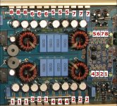
This is what I'm working with..
only numbers on the board are ILSIM_D2000_v40, that I can find that is...
An externally hosted image should be here but it was not working when we last tested it.
Hope that is ok
An externally hosted image should be here but it was not working when we last tested it.
There is also a smt 4558 right behind the rca jacks..
And also in the pic there is a smt 4558 under the black caps on the vertical mount board.
Last edited:
The 13600 is for the remote level control. The one behind the RCA jacks is likely for the input noise canceling circuit. The ones I expected to see would have been on the long driver board.
On the 3s-tech board I referred to, there is a problem with bad solder joints. this one may have the same problems.
The driver transistors (both large and small) run at high temperatures and the solder joints fail. I've also seen several of the smaller transistors fail (open, not shorted). There are probably 4 individual groups of outputs on each side of the amp. Each group is driven by it's own driver transistors. If you find faults and the amp begins to work, don't immediately consider it repaired. You MUST check the gate signal for EVERY output transistor to confirm that it has a strong signal. The amps will operate without having all of the outputs working (some with insufficient or no drive signal). If it's put back into service without ALL of the FETs being driven, the amp will fail.
A strong lighted magnifying glass helps when looking for failed solder connections.
In the attached photo, you can see how each of the 4 driver circuits correspond to groups of outputs. Yours should be roughly similar.
Attachments
An externally hosted image should be here but it was not working when we last tested it.
What are the specific devices I should focus on?
And I was just asking whether or not you think everything is good up to the drivers because the clipping light is showing a audio signal?
I will check the +- 15 volts and the black cap in the pic isnt blown its just been hit with a hot soldering iron by the previous owner.
Last edited:
The 4 small SMD transistors and the 8 large SMD transistors on each end of the board is where I'd begin looking. Many times, the ones that have been running the hottest are brown instead of gray but these all look gray.
Make sure all of the solder connections flow smoothly onto the leg of the transistors. Any that have lines/cracks around all or part of the leg need to be desoldered and resoldered.
Since these are self oscillating amplifiers, you may have to get enough of the drivers operating to allow it to oscillate. You'll have to reinstall the outputs for it to produce a high frequency drive signal. It may produce some low frequency signal if you drive it with a really strong RCA input (gain at the max position).
If all of the connections look OK, you'll need to check all of the transistors mentioned above. You will not only have to check for shorted transistors but also for open transistors. This means you'll have to look up the transistor to determine if it's NPN or PNP and confirm that both junctions are intact. Let me know if you need more details.
Did you check the comparator on the driver board? The LM293 is likely sitting on the negative rail so be careful when probing it's pins (don't slip and don't touch the metal part of the probes). If that's the case, measure the voltage from pin 4-8 instead of from ground to the pins.
If all of the connections looked OK and resoldering them didn't help, you may have other problems. For the amp to refuse to oscillate due to bad connections or open transistors, there would have to be several problems making multiple drive stages inoperative. I've never worked on one of these (with this driver board) but I'd have to guess that at least 2 of the ICs are in that gray box which is probably potted with epoxy. One of them could be defective.
For the driver transistors, check each one then reverse the probes on the same legs. Compare those readings to the others in similar locations (for each group of drivers). This should help you locate any open ones without desoldering anything.
I don't think there are any transistors significantly better than the ones they're using. As with any class D, It's generally best to use exact replacement parts (if you do need replacements).
The 1D and 2D are MMBTA42 and MMBTA92. The AG and DK are likely 2SA1797 and 2SC4672.
It looks similar to one of the 3s-tech boards but I'd expect to see 2 more 8 pin SMD ICs. Are there two ICs on the driver board that are hidden in this view?
if I remember correctly, I think these aren't korea made by 3Stech.
I've seen other Massive amps similar in guts to chinese Sound Magus.
- Status
- This old topic is closed. If you want to reopen this topic, contact a moderator using the "Report Post" button.
- Home
- General Interest
- Car Audio
- Massive D400x