Update
I switched the panelthat was not working earlier to the electronics that were recapped and this panel is now working however still having overheating issue with my amp. So, both panels are good but the electronics have issues. ..one must have a short, as Tyu suggested and the other I have to finish recapping.
I switched the panelthat was not working earlier to the electronics that were recapped and this panel is now working however still having overheating issue with my amp. So, both panels are good but the electronics have issues. ..one must have a short, as Tyu suggested and the other I have to finish recapping.
Further update
Finished recapping the other electronic plate and no sound came out of panel...just wooferis working as before.
Tyu, you said the spool of copper coil is an inductor. ...okay, so if the coil seems intact why would it need to be replaced? What would be wrong with it for it to need replacement. ..I must not understand the details. Also, if I need to replace it, where do I find the same one and how would it cost?
Update
I switched the panel that was not working earlier to the electronics that were recapped and this panel is now working however, still having overheating issue with my amp. So, both panels are good but the electronics have issues. ..one must have a short, as Tyu suggested and the other I have to finish recapping.
If one crossover was driven too the point of boiling like the other........you can bet the so call good crossover was driven by the same amp...........so ea crossover has bad parts!..........
Now you also have no way of knowing if the transfourmers are not also Bad...thay can still pass sound.... but could have been cooket also!........An be showing the amps... all most a short.........
I would not use my good amps to do anymore testing!.........
.What i do is use a old amp ...that if it dies i can live with!.......
You keep useing your good amps...you can kill them too!............more an more $$$ down the hole.......it you $$$........ i am just saying...ESL are great speaker...but thay need more lov than most..... to get some of the best sound on earth..............
just one mans o-pine..............
No amp can drive a short for long....All parts on ea. crossover boards need to be replaces......all.......... caps........coils....res.....
I have to say ....i have never seen any speaker crossover cooket like yours...an i was in the Audio bizz for 8 years....i seen a lot of speakers...............
Look to me some played the speakers......unpluged from the AC...no bias on the panels...........but who knows.........none of that matters now
good luck
Tyu your right and I have been using a much cheaper amp for the last few tests. Based on the ccurrent symptoms, would you say that the bias part of the electronics is good and the crossover part is the problem? Or is that still hard to determine? Either way, I'm going to try switching the bias boards then maybe the crossover boards to see what happens...I maybe able to get one working electronic plate at least.
Dont no.........
It not the point of geting one runing............................yes test all things. you can...but all parts need to be re-placet in the crossovers frist.......then ck the bias........then the tranfourmers..................... but this is just how I Would do it.............
at some point i think you need to have fun..................good luck
Why don't you just remove the toasted crossover board and keep the step up transformer with the R4 100K-ohm 50W & R5 5K-ohm 20W resistors on the secondary side of the circuit and use an active crossover?If I change the rest of the components, it may cost more than a new and I may still have a short in one of the traces.
.
Attachments

Hello X83,
That sounds like a great idea however, I don't think I would know how integrate the two. And I'm not sure if the transformers and the bias boards work properly. ..I would need both for your idea to work right? I see your schematic but I'm not sure I can make sense of it. I could probably be talked through it if you could call me. Please let me know if we can talk, as I would love to try your idea.
That sounds like a great idea however, I don't think I would know how integrate the two. And I'm not sure if the transformers and the bias boards work properly. ..I would need both for your idea to work right? I see your schematic but I'm not sure I can make sense of it. I could probably be talked through it if you could call me. Please let me know if we can talk, as I would love to try your idea.
It's just very simple wiring & soldering with the addition of another set of speaker binding posts.
- Remove the step up transformer from the crossover board.
- Remove the R5 5K-ohm 20W black colored ceramic resistor.
- Remove the R4 100 K-ohm 50W gold colored aluminum resistor.
- One set of binding posts gets directly hooked up to the woofer with the red (+) & black (-) wires.
- The other set of binding posts gets hooked up directly to the transformer with the green (+) & black (-) wires.
- The transformer red wire gets hooked up to the black ground wire going to the high voltage bias board.
- The blue color transformer wire and black stator panel wire gets soldered to one side of the R4 100 K-ohm 50W gold colored aluminum resistor.
- The brown color transformer wire gets soldered to the other end of the R4 100 K-ohm 50W gold colored aluminum resistor along with one end of the R5 5K-ohm 20W black colored ceramic resistor.
- The other end of the R5 5K-ohm 20W black colored ceramic resistor gets soldered to the blue stator panel wire.
Attachments

X83,
Sonds like a plan...I'll try tackling this later today. I hope I can follow it. Have you done this before...I just don't want to up in flames? So, this will bypass the crossover. ..how do I integrate a new crossover?
X83, does this mean that you think my transformers are in good working order..based on my info above?
Last edited:
I've used this method for all my Martin Logan speakers with an active crossover setup and it works much better than stock. Just make sure you keep the 100K-ohm resistor across the secondary's for magnetic inductance to keep the transformer from saturating and the 5K-ohm resistor on the front stator side for leakage inductance ultrasonic filtering.
I would ohm check the transformers once you have them removed between the blue & red wires which should be around 105-ohms. Then between the red & brown wires should be around 88-ohms. Then check to see if there's resistance between the green & black wires. If the transformers are defective you should consider replacing them with the Antek or VTX 230/6V power toroids which have about the same 1:70 step up ratio.
You will need to find an active crossover with a -24db Linkwitz/Riley filter and set it to around 250Hz. Also make sure the crossover has RCA or XLR or both type inputs & outputs then connect it between your pre-amp & amplifiers. You will also need use two stereo amplifiers or one four channel amp to power your speakers. If your pre-amp & amplifiers have XLR connections I would consider using the Art-CX310 or DBX-223s or Rane-AC23s or Ashley-XR1001 analog type active crossovers.
Okay great!X83
Just checked the resistance on one of transformers and the seem good about 108.6 and 89.0...between black and green, I got a resistance of 1.0. is that going to work?
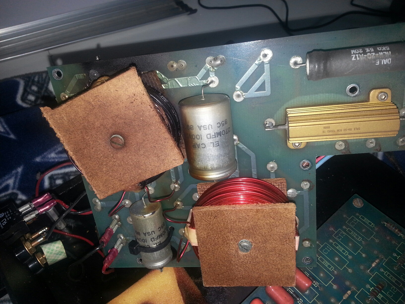
The two resistors are on the back side of the crossover board in this picture. One should be the Dale RH-50 50W 100K-ohm 1% #8926 gold colored aluminum resistor and the other is Dale HLW-20-A1Z 5K-ohm 5% 20W black ceramic type resistor. Make sure they're both within ohm specs.x83.
I just want to clarify that when you refer to the "100 k - ohm gold colored resistor" that is the same as my gold colored resistor which says "dale RH-50 50W 5-ohm" resistor?
Found them....good news is the the ceramic ones check out at 5.8 but the gold ones read nothing. BTW, the other transformer checks out okay. Looks like I'll need to pick up a couple of Dale RH- 50 50W 100k-ohm 1% resistors.
If I haven't said thank you your help already. .."thank you."
If I haven't said thank you your help already. .."thank you."
Found them....good news is the the ceramic ones check out at 5.8 but the gold ones read nothing. BTW, the other transformer checks out okay. Looks like I'll need to pick up a couple of Dale RH- 50 50W 100k-ohm 1% resistors.
If I haven't said thank you your help already. .."thank you."
Okay they have both been damaged and you should use a lower ohm value on the other side of the transformer.
I would order two Dale NH-25 25-Watt 1-ohm 1% resistors and two Dale RH-50 50-Watt 20-ohm 1% resistors.
You can install them both on the primary side of the transformer and it will make wiring them much easier.
NH0251R000FC02 Vishay / Dale | Mouser
RH05020R00FC02 Vishay / Dale | Mouser
Attachments

Last edited:
Ok, I'll order them. ...look inexpensive enough. I'm not sure want you mean by the "primary side" of transformer? Also, just so I have this right. ..at the end of the day I'll have the transformer connected to these resistors and the binding posts. Then I'll have the preamp feeding into the avtive 2 way crossover at about 250hz. From the crossover to the two amps...one connected to the hi pass feeding the panels and the other to the low pass feeding the woofers. I will not be using any other parts of the original electronics....rest of the crossover section and what I call the bias side with what looks like a smaller transfomer? Do you have any pics of a similar project that you can share with me?
- Status
- This old topic is closed. If you want to reopen this topic, contact a moderator using the "Report Post" button.
- Home
- Loudspeakers
- Planars & Exotics
- Martin Logan Sequel II dead panels