Hi,
I recently exchanged my old amp for a clone of what should be a 20Watt Marshall Plexi clone. Everything was excellent, it had this bright ear-hurting lead sound and a muddy rhytmic one. However, I had to move it from one room to another and when I plugged it in it had a distorted sound, of rather low volume, with a lot of harmonic harsh in the background. It seemed rather odd it had done this in a moment, because it was plugged in for an hour and acted excellent before the trade and in my home. I don't think it was any defected amp. I found the pot, which I think can be a bias or something - I had to move it nearly to the limit and it worked fine - but a bit muddy, it lost its brightness and volume. I know this pot works very quick, 0,5cm of turn and it goes from around 15V (when it sounds kinda allright) to 30V (it distorts badly or even stop to make a sound). The pot does not affect the voltages, so I think it's a bias pot.
I know, and I measured it has a mod - the 2x EL34 works on 560V plate voltage. I can't find a spot in which I can measure a voltage drop - it has always 560V or 2x 280 in every place where high voltage goes.
There seems also to be strange thing, in my opinion making the sound that muddy and and not loud - there is a 64V, 56V and 50V on 12AX7 which makes a preamp (from third in a stage to first I think) - it looks terribly low.
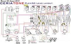
Do you have any suggestions what to check, change or anything? I think it's a variation of layout i post here. The ceramic resistors are 10K, the pot in it's position is something about 5k, big caps on board are 100uf/385V. Some values are other than on the layout I post, but it's really close.
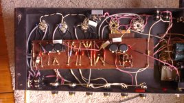
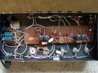
All connections seem pretty allright. The "bias pot" is without it's case behind big right caps, left to the two small caps. I'm sorry for quality of photo, looking for a camera.
I recently exchanged my old amp for a clone of what should be a 20Watt Marshall Plexi clone. Everything was excellent, it had this bright ear-hurting lead sound and a muddy rhytmic one. However, I had to move it from one room to another and when I plugged it in it had a distorted sound, of rather low volume, with a lot of harmonic harsh in the background. It seemed rather odd it had done this in a moment, because it was plugged in for an hour and acted excellent before the trade and in my home. I don't think it was any defected amp. I found the pot, which I think can be a bias or something - I had to move it nearly to the limit and it worked fine - but a bit muddy, it lost its brightness and volume. I know this pot works very quick, 0,5cm of turn and it goes from around 15V (when it sounds kinda allright) to 30V (it distorts badly or even stop to make a sound). The pot does not affect the voltages, so I think it's a bias pot.
I know, and I measured it has a mod - the 2x EL34 works on 560V plate voltage. I can't find a spot in which I can measure a voltage drop - it has always 560V or 2x 280 in every place where high voltage goes.
There seems also to be strange thing, in my opinion making the sound that muddy and and not loud - there is a 64V, 56V and 50V on 12AX7 which makes a preamp (from third in a stage to first I think) - it looks terribly low.
Do you have any suggestions what to check, change or anything? I think it's a variation of layout i post here. The ceramic resistors are 10K, the pot in it's position is something about 5k, big caps on board are 100uf/385V. Some values are other than on the layout I post, but it's really close.
All connections seem pretty allright. The "bias pot" is without it's case behind big right caps, left to the two small caps. I'm sorry for quality of photo, looking for a camera.
Attachments
Hi Guys
The bias pot is nothing to be twiddled lightly.
The 1R resistor from pin-8 to ground of each power tube socket is there to provide safe ground-referenced measurement of the idle current of the tube. Bis is set with the input volumes or MV set to zero, no signal.
Use an alligator test lead to clip the negative lead of your meter to ground. This means you have only one hand in the live chassis.
Use a DC voltmeter to first set the voltage at pin-5 of either tube to the maximum negative value.
Next, measure the plate supply voltage. Best to probe on the filter cap or the output of the main rectifier. Note this voltage.
Each power tube has a plate power rating. The layout is for a 50W amp and the B+ looks to be about 450V. if you have EL-34s in place, these have a plate rating of 25W, which just means the plate of the tube can throw off 2W of heat and means nothing about the output power that be attained in audio watts.
25W at 450V corresponds to a current of 55mA. This is the maximum current allowable at idle for this tube at this voltage. If the supply voltage was half as high, current could be doubles; if the voltage was doubled then current would be halved. This is just standard power equations and Ohm's Law.
Generally, the idle current is set so that the dissipation is not at maximum but rather a half or a bit higher. This means your target current reading would be more like 27-35mA.
Because those 1Rs are in place, you will not be measuring current, rather voltage. Each 1mVdc = 1mAdc through the tube. So, you will be looking for a reading of 27-35mVdc when you probe either of the octal socket pin-8s.
You cannot set bias by looking at the grid control voltage as that does not tell you how hot the tube is running. Only measuring the tube current and knowing the plate voltage will provide TRUE information about if the tube will be safe.
Usually, when a move is made as you describe and the amp then does not work or sound okay, it is just a bad tube, or a tube is loose in its socket. Combo amps are the worst environment for tubes.
Have fun
Kevin O'Connor
The plate voltage is 560V. I said this is somehow modified version of the layout I posted. Setting the pin 5 to the lower voltage distorts the signal. It can be done by turning the pot I was talkin about and it sound the best when it's fully turned.
I really don't think it's a tube because the problem just magically appeared.
There I think it's also the preamp section low voltage issue.
Are there any other ideas?
Edit: wow, wow the preamp is made using 6n2p tubes
I really don't think it's a tube because the problem just magically appeared.
There I think it's also the preamp section low voltage issue.
Are there any other ideas?
Edit: wow, wow the preamp is made using 6n2p tubes
Last edited:
The DC meter does not show a stable voltage, it goes from 27-32mV across the 1R resistor (but it goes from pin 5 control grid to unused pin 6?) and seems to be OK then with voltage of 560V. I think that stage is working OK . The 100K pot about which I was talking sets the grid 1 (control grid pin5) minus voltage (now it's about -12V, then it was about -30 to -50V and worked like a crap).
What should the voltages been then?
What should the voltages been then?
Last edited:
Hi Guys
Renloo, there is missing information in your statements about this amp, and you seem to have a total disregard for the safety of the tubes as outlined above.
According to the layout drawing you posted, B+ should be around 450V. Look at the lower right corner of the PT and see 325-0-325. The 325 lines go to each end of the half-bridge rectifier; 0 goes to chassis ground. 325Vac becomes about 450Vdc once rectified and filtered - NOT 560V.
Measure pin-4 of the output tubes. if your claims about the grid voltage (pin-5) is correct then pin-4 should be around 280V.
If the above screen voltage is half the plate voltage (280Vs, 560Va) then the supply is quite different, more like the high-voltage Marshalls from the late '70s. If this is the case, and Vs is only 280V or so, then you would expect to see about -30-35V at pin-5 to keep the tubes from melting down.
-12V on the control grid makes no sense whatsoever - the tubes would be red-plating!
It is more likely that you are not using a proper reference point for the meter readings, or that the circuit ground is liftable from the chassis ground via an undisclosed ground-lift switch (usually on the rear panel), or that your meter is not working, or that you don't know how to use the meter.
You MUST turn the volume controls on the amp to zero to make proper voltage measruements, otherwise you are measuring noise. This is especially important when checking the pin-8 voltages on the outputs.
Have fun
Kevin O'Connor
According to the layout - I said it is very similiar but have mods - like a higher voltage. So it's different. I looked for bias and for 560V on plate it should be around -25V (class AB) on the grid - then the amp is silent. It is set -25V now.
I don't run it at -12V because I know it's bad and it don't behave good way - so I don't run it like this, I just said then it starts to work, which maybe can be a clue.
There is no ground-lift switch, I know how to use the meter, the ground is perfectly ok.
I have turned the volume controls to zero, according to first reply.
I had checked the preamp and it is adjusted to work with those voltages.
It is my first time working with tube output stage, however I managed to find some good article about biasing now, because the problem lies propably there and everything should be brought back to normal...
The plate voltage is 560V. I said this is somehow modified version of the layout I posted. Setting the pin 5 to the lower voltage distorts the signal. It can be done by turning the pot I was talkin about and it sound the best when it's fully turned.
I really don't think it's a tube because the problem just magically appeared.
There I think it's also the preamp section low voltage issue.
Are there any other ideas?
Edit: wow, wow the preamp is made using 6n2p tubes
Tubes can go bad at any time for any reason. Don't rule out a simple tube swap to fix the problem.
I have passive pickups, so nothing to worry about battery ") I ordered a set of 6n2p in fact but buying EL's would be pretty a pain (having holiday and only spending money ). I luckily found a producer of amp so after a contact propably I will have a schematic or any other info.
I ordered a set of 6n2p in fact but buying EL's would be pretty a pain (having holiday and only spending money ). I luckily found a producer of amp so after a contact propably I will have a schematic or any other info.
I ordered a set of 6n2p in fact but buying EL's would be pretty a pain (having holiday and only spending money ). I luckily found a producer of amp so after a contact propably I will have a schematic or any other info.Did anyone notice the bridge rectifier in the heater lines between the power tubes and the phase inverter? I don't see a filter cap anywhere for the preamp heaters. What DC volts do you measure between pin 9 of one of the preamp tubes and pins 4 and 5? What does each side measure to ground?
Hi Guys
It is still disturbing that you have not measured the screen voltage and that you report twiddling grid bias to -12V. If Vs is 280V, then -12V on the grid should red-plate the output tubes.
I told you how to bias the tubes above.
Because the "problem" appeared right after you moved the amp, the FIRST suspect is tubes. Tubes will last forever electrically provided they are not mechanically upset.
Feeding pulsating DC to the heaters is asking for increased possibility of noise intrusion from the heaters to the grids due to the discontinuities of conduction caused by the rectifier. These can be smoothed using resistors, or eliminated by adding a filter cap.
Have fun
Kevin O'Connor
3,15V on both pins, so it works on 6,3V accurately
3.15VAC on each side does not tell us what the DC voltage is between pin 9 and pins 4 and 5. The AC voltage reading suggests that the heater winding has a center tap that is grounded. Hopefull the builder did not ground the minus side of the bridge. That would probably damage the bridge or the transformer.
Hi Guys
How is the 11Vs created? From a separate winding on the PT?
This is very low and may restrict how much output power is attained using a standard splitter. It does howver explain how you can set the grid voltage to -12V without red-plating.
Matched tubes are a waste of money - others will disagree. It is far better to have separate bias adjustments for each tube so they can be set to the hum-balance point of the OT. Tubes drift with age, especially in a combo amp, and matched tubes will rift apart.. Separate bias also allows using other tube types and to mix tube types.
Have fun
Kevin O'Connor
I think I would make a separate bias adjustment after having this amp sing back again. I know it's better.
I think the voltage can be so low because it was meant to give power around 20W, not 50W common in 2xEL34. However I can be wrong. The 115V comes from the "psu board" seen in the left top corner. (The another point on board gives plate voltage of 560V.) Then the voltage goes through, I think choke and then to grid. It also supply the anode voltage of preamplifier.
Preamplifier uses DC heaters, it's 6n2p (no center tap) and beetween 4 and 5 pin there is 6,5V.
Hi Guys
Plate or screen voltage being low is fine. The problem is you've posted a layout that does not match your PSU. Maybe you should trace it?
If the original PT provided 50W with screens at a more usual voltage, it may be possible to power the whole amp from the 280V CT and have quarter power - about 12W. Have you verified the output power as the amp is wired now? or are you just happy that it is may be tolerable?
The Marshalls that had 560V for the plate and screen usually had a 100V winding for bias. I assume this is being used for the screens in your amp. If they used half-wave rectification from this winding, you get a low voltage - as you have - but can also still generate the bias voltage from it.
When setting idle current, remember to use the 560V as part of the calculation, since this is the plate voltage in your amp. Actually, did you measure 560V at idle on pin-3 of either octal socket, or just at the supply? It is more telling at the socket itself.
Be careful not to let the meter lead slip and short the tube pin to chassis.
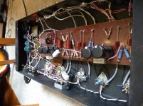
Some of the wiring is pretty lousy - certainly not low-noise promoting. More like a Diaz amp...
Have fun
Kevin O'Connor
Plate or screen voltage being low is fine. The problem is you've posted a layout that does not match your PSU. Maybe you should trace it?
If the original PT provided 50W with screens at a more usual voltage, it may be possible to power the whole amp from the 280V CT and have quarter power - about 12W. Have you verified the output power as the amp is wired now? or are you just happy that it is may be tolerable?
The Marshalls that had 560V for the plate and screen usually had a 100V winding for bias. I assume this is being used for the screens in your amp. If they used half-wave rectification from this winding, you get a low voltage - as you have - but can also still generate the bias voltage from it.
When setting idle current, remember to use the 560V as part of the calculation, since this is the plate voltage in your amp. Actually, did you measure 560V at idle on pin-3 of either octal socket, or just at the supply? It is more telling at the socket itself.
Be careful not to let the meter lead slip and short the tube pin to chassis.
Some of the wiring is pretty lousy - certainly not low-noise promoting. More like a Diaz amp...
Have fun
Kevin O'Connor
It was of course measured at pin-3. I traced every voltage up to power section, just to be sure if everything is ok, and it is. I have found the producer and asked for a schematic and some information, maybe I would know something more.
I use very sensitive speakers, around 101dB/1W/1m and amp itself is dead silent. Guitar is a pretty noisy stuff and with it is ok, even better than solid-state Hartke I used before. I don't think there is a need to twist the wires to the limit.
The output power is OK with me, using 50W at home with guitar cabinet is just a problem. Now I'm waiting for the tubes, every set is already sent
First I want it too let it play correctly, then there will be time to make any mods, corrections and so on.
I'm very happy you guys try to help
- Status
- This old topic is closed. If you want to reopen this topic, contact a moderator using the "Report Post" button.
- Home
- Live Sound
- Instruments and Amps
- Marshall Plexi Clone