Interesting attitude.
Youre saying its not simple ??
May I show some circuits here that I believe will equal and perhaps better this design ?? I cannot promise that a circuit virtually identical to yours wont come up though.
This is easily achieved, Im dumfounded when you make it seem likes its a miracle or something only known to a select few or something.
One more time: achieve it, and submit it to LA so that we all can judge

As far as the RM's amplfier is concerned, would you please show me the exact point where I wrote It's a miracle!!! ...? I've only pointed out that it seems there is quite a bit of good engineering behind it.
L.
One more time: achieve it, and submit it to LA so that we all can judge
As far as the RM's amplfier is concerned, would you please show me the exact point where I wrote It's a miracle!!! ...? I've only pointed out that it seems there is quite a bit of good engineering behind it.
L.
What is it with you and having to submit stuff to LA for judging? If I had a miracle circuit do you think I'd share it with anyone? Hell no. I'd patent it. If it was merely pretty good and used standard circuits, then I just post it here. You make it seem like a miracle by continuously challenging other people to submit to the "iron test" of getting their circuits published in LA.
There's a hell of a lot of good engineering behind any of a million other circuits as well. What's your point?
Youre saying its not simple ??
May I show some circuits here that I believe will equal and perhaps better this design ?? I cannot promise that a circuit virtually identical to yours wont come up though.
If you're willing to share, I'm willing to learn.
The generosity of sharing circuits is how we all learn.
I can't find the post where I said that. Can you provide a link?
When you said: "Ed's point is that a sim is nice, but real pieces of silicon, carbon, and copper may not give you what the sim predicts. RM's circuit performance as a real, built item is outstandingly good." you suggested that simulated circuits always perform better than real ones. My assumption is that you meant that the performance of a real circuit would be worse than the simulated one. If you mean otherwise, then please elaborate.
One more time: achieve it, and submit it to LA so that we all can judge
As far as the RM's amplfier is concerned, would you please show me the exact point where I wrote It's a miracle!!! ...? I've only pointed out that it seems there is quite a bit of good engineering behind it.
L.
Youre joking right
Thats exactly what you make it sound like, offcourse there is some engineering behind it but at present time (2012) this is pretty basic stuff for those in the art.
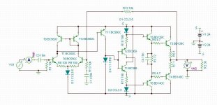
:OK, if we're playing around with headphone amps, I really don't see a need for more than 6dB of gain. Unity gain would be fine actually. This one has 2.7x10^-5% (0.000027%) distortion @1kHz, 990mVrms into 30 ohms with 6dB of gain. It's nothing fancy. DC offset on the output is less than 1mV (730uv). Bandwidth shows a very mild bump @ 10MHz. No biggie in my opinion.
Attachments
Last edited:
When you said: "Ed's point is that a sim is nice, but real pieces of silicon, carbon, and copper may not give you what the sim predicts. RM's circuit performance as a real, built item is outstandingly good." you suggested that simulated circuits always perform better than real ones.
How exactly does MAY not suggest always?
Please look up the word "may" and get back to us.
se
If you're willing to share, I'm willing to learn.
The generosity of sharing circuits is how we all learn.
The Class-A Amplifier Site - JLH Headphone Amplifiers
I thought everyone was aware of these simple circuits. This one dates from 1969.
Here is a good place to start, look at figure 2, tweak it, make the output a cfp, bias the output hot, 100 ma or even more, mje172 series is excellent for the job, its not not too difficult to get .001 thd into 30ohms ( depends much on output bias current. Use hig beta input transistors to get high input impedance like bc550 series and bigger caps like 2200 uf
One you have in simmed and seen the in and outs you can add simple features that will make it even better. No 18 transistors needed
OK, if we're playing around with headphone amps, I really don't see a need for more than 6dB of gain. Unity gain would be fine actually. This one has 2.7x10^-5% (0.000027%) distortion @1kHz, 990mVrms into 30 ohms with 6dB of gain. It's nothing fancy. DC offset on the output is less than 1mV (730uv). Bandwidth shows a very mild bump @ 10MHz. No biggie in my opinion.
Seems you dont need much help, you have the right idea, thats one way to go about it, its pretty simple reaching the figures mentioned here with headphone amps.
Last edited:
When you said: "Ed's point is that a sim is nice, but real pieces of silicon, carbon, and copper may not give you what the sim predicts. RM's circuit performance as a real, built item is outstandingly good." you suggested that simulated circuits always perform better than real ones.
"Different" is not synonymous with "Better."
How exactly does MAY not suggest always?
Please look up the word "may" and get back to us.
se
Using "may not" makes the reader think the writer sees the subject as pessimestic. If you used "may well" it does just the opposite.
Same type of situation like telling someone the price is only 19.99 $ instead of 20$. The difference is only 1 cent but its proven that over 60 percent of people fall for the .99. Thats the reason you see on all department stores, well virtually any commercial enterprise advertise everything with the famous .99. After all the years it still to works.

OK - forget about LA: posting to diyaudio a working circuit that's not pretty basic stuff for those in the art will be fine too (and I'm afraid DB, VF topologies with DB output buffer and the like * do are * pretty basic stuff for almost everyone here...). Nothing miracolous about RN's amplifier - do not have the last LA issue on my desk, but from what I've seen (and read) it seems only a well engineered simple and clever circuit that works really fine: something different from the same old discrete VF power opamp, which is one of the reasons why I'd give it a try. It's probably nor the best neither the worst way to do a headphone amp, but simply one of the ways to do it - I went for a crazy CF open-loop topology, other guys may well go for something entrirely different: there's more than...
Anyway it seems I don't see your point and you don't see mine - all in all it's fine for me: I'm a physicist and do love symmetry so much...
L.
Anyway it seems I don't see your point and you don't see mine - all in all it's fine for me: I'm a physicist and do love symmetry so much...
L.
If I had a miracle circuit do you think I'd share it with anyone? Hell no. I'd patent it.
Interesting pair of opinions.If you're willing to share, I'm willing to learn.
The generosity of sharing circuits is how we all learn.
The Class-A Amplifier Site - JLH Headphone Amplifiers
I thought everyone was aware of these simple circuits. This one dates from 1969.
Here is a good place to start, look at figure 2, tweak it, make the output a cfp, bias the output hot, 100 ma or even more, mje172 series is excellent for the job, its not not too difficult to get .001 thd into 30ohms ( depends much on output bias current. Use hig beta input transistors to get high input impedance like bc550 series and bigger caps like 2200 uf
No 18 transistors needed
Jaha! The buffer shown earlier in this thread is just a beefed up version of the one shown in your link at the bottom of the page.
Interesting pair of opinions.
Right, so the upshot is that the only things to be shared are the ordinary...
Seems you dont need much help, you have the right idea, thats one way to go about it, its pretty simple reaching the figures mentioned here with headphone amps.
Thanks! Always more to learn though.
The Class-A Amplifier Site - JLH Headphone Amplifiers
I thought everyone was aware of these simple circuits. This one dates from 1969.
Gosh! Why not a low power Williamson, maybe with a Kappler phase splitter? Or an Olson with a single pair of 6F6s on output?
Seriously speaking: I do love the JLH - built it in 1978, some 34 years ago, when I was very very young...
Now I feel the time is right for moving to something different, just for the sake of curiosity, or maybe just to keep myself alive and kicking... L.
Gosh! Why not a low power Williamson, maybe with a Kappler phase splitter? Or an Olson with a single pair of 6F6s on output?
Seriously speaking: I do love the JLH - built it in 1978, some 34 years ago, when I was very very young...
L.
Oh I have , I took that circuit and gave it much better performance. At solidstate there is currently two designs being developed around the basic scheme as shown and those involved love it, see TSSA thread. Funny how after all the years nothing as simple and good performing has come up and how many are only now discovering it.
I thought sharing how to make a circuit topology perform to its best potential was a lot of what this site was all about. Am I in the wrong place?If you're willing to share, I'm willing to learn.
The generosity of sharing circuits is how we all learn.
Last edited:
- Home
- Amplifiers
- Headphone Systems
- Marsh headphone amp from Linear Audio