Thanks for the tip.
Were you running linear voltage regs after the Meanwell, or directly wired to the board?
Using one for the stereo circuit, or one per channel?
For the tests i ran it without post-regulators. this dc-dc converter is good for 400mA
For the tests i ran it without post-regulators. this dc-dc converter is good for 400mA
Thanks for the info. Ordered one converter from Jameco and is on its way.
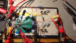
My intent is not to re-engineer the working circuit, but to replicate what has been built and measured, and listen to it first for a baseline.
I've noticed something about this amplifier that I'm curious about.
When feeding it a 2V signal through a 10K volume pot, the sound is somewhat harsh and almost distorted.
Is it possible that the input stage is being overdriven?
I do not have a scope or any other fancy test equipment to check it with.
When feeding it a 2V signal through a 10K volume pot, the sound is somewhat harsh and almost distorted.
Is it possible that the input stage is being overdriven?
I do not have a scope or any other fancy test equipment to check it with.
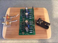
Steve,Well, the PCB and DC-DC converter is assembled now . . . Waiting now on a 12V 2A wall wart and a 1/4 stereo phono jack.
I just finished soldering up my boards this weekend and still need to build the power supply. Like you, I'm waiting for a few parts. I took a quick look at your build and noticed that you seem to have put in jumpers shorting the two vias close to the potentiometers p1 and p2. Is that for connecting power ground to signal ground? I missed the discussion about these jumpers.
---Gary
A genuine breadboard layout. Sorry, I could not help myself. I have been following this post with interest. Thanks for sharing.
Its a teak coaster from Bed Bath and Beyond. Only a couple of bucks, and great to do small layouts on.
Steve,
I just finished soldering up my boards this weekend and still need to build the power supply. Like you, I'm waiting for a few parts. I took a quick look at your build and noticed that you seem to have put in jumpers shorting the two vias close to the potentiometers p1 and p2. Is that for connecting power ground to signal ground? I missed the discussion about these jumpers.
---Gary
JackinNJ covers this back starting at post #293. There is another jumper near the input, per channel too. They tie ground together for each individual channel. Then both channels then need to grounded, at the star ground/CT as outlined by Richard Marsh.
Its a teak coaster from Bed Bath and Beyond. Only a couple of bucks, and great to do small layouts on.
You need to find a Home Depot, or a town dump.
btw, whatever happened to Fahnestock clips?
I live less than a quarter mile from a HD. They don't stock teak in the lumber yard.
Thanks for the tip on Fahnestock clips. Seen them before, never knew the name.
Nice execution of Richard's published design, Jack. Everything went together well, and some quality parts there. Looking forward to powering it up in a few days and giving it a listen.
Thanks for the tip on Fahnestock clips. Seen them before, never knew the name.
Nice execution of Richard's published design, Jack. Everything went together well, and some quality parts there. Looking forward to powering it up in a few days and giving it a listen.
FYI - higher PS voltages
Here is something I did a couple days ago because i was curious and others might want to experiment.
I tried some options for transistors. I found that the yield for matched fets was higher when using the 2N5458 and 2N5462 for J1 and J2. And, Q1 and Q2 can be BC560C and BC550C. I tried higher voltage output devices so I could run up the power supply voltages.... more headroom and lowers the THD further. With the orignal transistors you can run at 15vdc... in fact I ran the whole circuit at +/- 24vdc with out blowing up the output devices. For the original device choices, 18vdc PS seems like a sweet spot for lowest THD.
I did a quick test using the above transistors with higher voltage OPS transistors... Q3,6 were 2SC5694 and Q4,5 were 2SA2037. I didnt match them.... though they should be for lowest distortion.

 Using 24vdc supplies. Unmatched OPS transistors.
This higher voltage reduced the THD compared to lower PS voltage and allows lower Z loads with minimal affect on THD. Greater heat-sinking would be required. At 18vdc, the THD was in the .001x range.
THx-RNMarsh
Here is something I did a couple days ago because i was curious and others might want to experiment.
I tried some options for transistors. I found that the yield for matched fets was higher when using the 2N5458 and 2N5462 for J1 and J2. And, Q1 and Q2 can be BC560C and BC550C. I tried higher voltage output devices so I could run up the power supply voltages.... more headroom and lowers the THD further. With the orignal transistors you can run at 15vdc... in fact I ran the whole circuit at +/- 24vdc with out blowing up the output devices. For the original device choices, 18vdc PS seems like a sweet spot for lowest THD.
I did a quick test using the above transistors with higher voltage OPS transistors... Q3,6 were 2SC5694 and Q4,5 were 2SA2037. I didnt match them.... though they should be for lowest distortion.

 Using 24vdc supplies. Unmatched OPS transistors.
 This higher voltage reduced the THD compared to lower PS voltage and allows lower Z loads with minimal affect on THD. Greater heat-sinking would be required. At 18vdc, the THD was in the .001x range.
THx-RNMarsh
Last edited:
Bias - temp
I forgot to mention.... I was using only 2 biasing diodes for OPS bias with these OP transistors. These transistors turn on sooner than the originals. At +/-18vdc the temperature is 125 degrees Fahrenheit without heat sink.
-RM
Here is something I did a couple days ago because i was curious and others might want to experiment.
I tried some options for transistors. I found that the yield for matched fets was higher when using the 2N5458 and 2N5462 for J1 and J2. And, Q1 and Q2 can be BC560C and BC550C. I tried higher voltage output devices so I could run up the power supply voltages.... more headroom and lowers the THD further. With the orignal transistors you can run at 15vdc... in fact I ran the whole circuit at +/- 24vdc with out blowing up the output devices. For the original device choices, 18vdc PS seems like a sweet spot for lowest THD.
I did a quick test using the above transistors with higher voltage OPS transistors... Q3,6 were 2SC5694 and Q4,5 were 2SA2037. I didnt match them.... though they should be for lowest distortion. About 145 F at 24vdc without heat sink.
View attachment 438274
View attachment 438275 Using 24vdc supplies. Unmatched OPS transistors.
This higher voltage reduced the THD compared to lower PS voltage and allows lower Z loads with minimal affect on THD. Greater heat-sinking would be required. At 18vdc, the THD was in the .001x range.
THx-RNMarsh
I forgot to mention.... I was using only 2 biasing diodes for OPS bias with these OP transistors. These transistors turn on sooner than the originals. At +/-18vdc the temperature is 125 degrees Fahrenheit without heat sink.
-RM
Last edited:
More than 50 Celsius; should be about the same here.
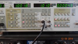
Just checked the datasheets of the output devices you used and compared them to those of the mfg of the parts I used... More than 200MHz fT and hFE in excess of 100 ain't nothing like 60MHz and 40 - guess why my THD measurements are worse than yours ...
...
Just checked the datasheets of the output devices you used and compared them to those of the mfg of the parts I used... More than 200MHz fT and hFE in excess of 100 ain't nothing like 60MHz and 40 - guess why my THD measurements are worse than yours
See here
http://www.diyaudio.com/forums/head...eadphone-amp-linear-audio-27.html#post3968382
and here
http://www.diyaudio.com/forums/head...eadphone-amp-linear-audio-27.html#post3967617
FETs are matched,
http://www.diyaudio.com/forums/head...eadphone-amp-linear-audio-26.html#post3956273
BJTs are BC550/560 and BD131/132, unmatched.
EDIT: PS voltage is a little low due to the high bias current. Running at 10.5V each.
- Home
- Amplifiers
- Headphone Systems
- Marsh headphone amp from Linear Audio
