Hola Symphony,
a pretty interesting behaviour - as I understand all three channels have the same effect that the positive voltage decreases from 16 to 9 Volt; have you measured the POS_REG as well as the POS_PRE_REG voltages under the condition of activated relays in all channels? If there is no substantial decrease in these voltages I would check R506 (its a wire wound resistor with some dissipation) and check the value (1,8kOhm )as well as the soldering around (maybe the solderings are not well contacted due to hot/cold cycles). CR504 is a 5Watt 16V Zener diode which should be pretty robust. Btw, what is the voltage on POS_REG?
When I look at Power supply schematics, the plus/minus voltage for the 5 channel amp should be a bit below 50 V due to the max voltage of the 17000uF caps; is this the same for the 3 channel amp?
atentamente
Dieter
ok......
Voltage after 317T/337T regulation is 77+77v in HPA and 55+55v in AMP5
when the relays activate, the +16v drops to +9v but the +77v remain stable. The 16v zener diodes are new x 5W. ....R504,R505,R506 are new.
I have resoldered and checked the board.
I have checked the relays, their coils are 1k and resistors R26 and R27 are OK.
U300 is new. U301 is the original.
I have seen in the Levinson 431 circuit that it has in the +16v regulation, 3 resistors of 2k2 in parallel. I have done this and managed to get +15v.
Thanks!!!....")
Voltage after 317T/337T regulation is 77+77v in HPA and 55+55v in AMP5
when the relays activate, the +16v drops to +9v but the +77v remain stable. The 16v zener diodes are new x 5W. ....R504,R505,R506 are new.
I have resoldered and checked the board.
I have checked the relays, their coils are 1k and resistors R26 and R27 are OK.
U300 is new. U301 is the original.
I have seen in the Levinson 431 circuit that it has in the +16v regulation, 3 resistors of 2k2 in parallel. I have done this and managed to get +15v.
Thanks!!!....
Yes....but that would not be a good solution.Congrats! so reducing the total resistor value between POS_REG and POS_16V to about 730 Ohms solved the problem!
all the Best
Dieter
The resistances raise their temperature quickly and cannot be touched. This will continue to damage the board from the high temperature. I can't understand who made this design.....
Interesting - the power supply diagram of the 5 channel amp shows 50V caps, which must be definitely wrong, otherwise you would get a hand grenade due to over voltage on these parts
Try to increase the value as high as possible to minimise the dissipation (3 resistors 2k7 in parallel), another possibility is to change the mains supply voltage of the amp to 240V (if possible) which will decrease the power dissipation as well.
Redesigning of the amp is a bit too much -
Try to increase the value as high as possible to minimise the dissipation (3 resistors 2k7 in parallel), another possibility is to change the mains supply voltage of the amp to 240V (if possible) which will decrease the power dissipation as well.
Redesigning of the amp is a bit too much -
Hello LJYS, Dieter,
good news so far 😊. After getting Q106 replaced - leave this job to an expert - my 432 now shows 500mV on TP8 on left and right channel daughter board, All other values are also as expected. The amp now goes out of standby and stays on permanently (red LED permanently on) without triggering the self-protection of the amp. Thank you LJYS for pointing me in the right direction.
I did not connect the speakers yet, so I cannot be sure if really everything is working but is looks promising. Before I connect the seakers I would first like to set the left and right channel Bias and here I have a question.
LJYS,
the instructions you kindly shared for setting the Bias state this:
"Set the DMM to “mVDC” and connect it between the hook on the RIGHT channel’s RED binding post and one of the emitter resistors on the RIGHT channel (R322, R318, R314, R310)."
Question: When I use R322 for this, on which side of the resistor R322 do I take the Bias measurement?
If it is the resistor side that is connected to the emitter, then I can simply take this measurement at Pin 3 (emitter) of Q311 which is openly accessible.
If it is the resistor side that is connected to V_OUT, then I would have to solder in a cable onto that end of the resistor R322 to take this measurement.
Note: It is my amateur understanding that the Bias is set with the amp turned on (red LED permanently on), I hope this is correct.
After I have gone though setting the Bias I still need to ensure the left channel voltage regulator VR1 sits flat on the thermal pad, currently it does not and the left side VR1 gets warmer than the right side VR1. And I still need to replace the thermal pad on the left channel. I had to damage the thermal pad a little with a knife in order to get the left audio channel transistors off from the thermal pad prior to getting VR1 and VR2 replaced. After that I will hook up the speakers to see what happens when I connect the speakers and play some music.
Best regards,
Mischa
E pin of measuring point MJL3281AHello LJYS, Dieter,
good news so far 😊. After getting Q106 replaced - leave this job to an expert - my 432 now shows 500mV on TP8 on left and right channel daughter board, All other values are also as expected. The amp now goes out of standby and stays on permanently (red LED permanently on) without triggering the self-protection of the amp. Thank you LJYS for pointing me in the right direction.
I did not connect the speakers yet, so I cannot be sure if really everything is working but is looks promising. Before I connect the seakers I would first like to set the left and right channel Bias and here I have a question.
LJYS,
the instructions you kindly shared for setting the Bias state this:
"Set the DMM to “mVDC” and connect it between the hook on the RIGHT channel’s RED binding post and one of the emitter resistors on the RIGHT channel (R322, R318, R314, R310)."
Question: When I use R322 for this, on which side of the resistor R322 do I take the Bias measurement?
If it is the resistor side that is connected to the emitter, then I can simply take this measurement at Pin 3 (emitter) of Q311 which is openly accessible.
If it is the resistor side that is connected to V_OUT, then I would have to solder in a cable onto that end of the resistor R322 to take this measurement.
Note: It is my amateur understanding that the Bias is set with the amp turned on (red LED permanently on), I hope this is correct.
After I have gone though setting the Bias I still need to ensure the left channel voltage regulator VR1 sits flat on the thermal pad, currently it does not and the left side VR1 gets warmer than the right side VR1. And I still need to replace the thermal pad on the left channel. I had to damage the thermal pad a little with a knife in order to get the left audio channel transistors off from the thermal pad prior to getting VR1 and VR2 replaced. After that I will hook up the speakers to see what happens when I connect the speakers and play some music.
Best regards,
Mischa
The red LED is always on is correct
After adjusting the voltage of all levels during standby, adjust the bias voltage after turning on the machine.
When the voltage is adjusted, the standby needs to be warmed up for half an hour, and the adjustment is repeated.
When the bias voltage is adjusted, it takes half an hour to warm up the engine and repeat the adjustment.
Hi Mischa,
concerning the bias adjustment there should be no problem connecting to the emitter directly as this pin is available; you could also connect to the emitter of the other power transistors as they should be selected, i.e. this should have very similar characteristics, which means you should measure very similar voltage between the red binding post and the emitters of Q301,303,305,.....313. As LJYS already pointed out the system should be warmed up anyway.
VR1 should under all circumstances mounted on the heat sink as to bring away the heat!
best regards
Dieter
Thanks you Dieter and LJYS for your help and advise.
I adjusted the Bias a few minutes ago, after warming up the amp as per instructions.
Left side was 15mV, now adjusted to 9mV. Right side was 10mV, now adjusted to 9mV.
I will take another measurement later using a different emitter pin.
Also I will look around among my friend for some old/inexpensive speakers, I would like to use inexpensive speakers for a first test with music going though the amp.
Regarding VR1, the person who replaced VR1 for me was a professional with the solder iron, but unfortunately did not pay enough attention to getting the height of the legs perfectly right as we were chatting away at the time. The legs of VR1 are now longer than then should have been. I did already bend the legs into an S shape but I need to bend them some more to get VR1 flat onto the thermal pad.
Taking of things that get warm, while adjusting the Bias I notice that CR119, CR120 really do get warm. Both left and right channel are the same so maybe this is normal.
In any case, if I get my 432 working again I promised myself that I will mount two small ventilators under the amp, one on each side, to ensure that there is always some air ventilation inside the amp. This I hope will help extend the life of my amp.
Best regards,
Mischa
It is normal for CR119 and CR120 to work very highThanks you Dieter and LJYS for your help and advise.
I adjusted the Bias a few minutes ago, after warming up the amp as per instructions.
Left side was 15mV, now adjusted to 9mV. Right side was 10mV, now adjusted to 9mV.
I will take another measurement later using a different emitter pin.
Also I will look around among my friend for some old/inexpensive speakers, I would like to use inexpensive speakers for a first test with music going though the amp.
Regarding VR1, the person who replaced VR1 for me was a professional with the solder iron, but unfortunately did not pay enough attention to getting the height of the legs perfectly right as we were chatting away at the time. The legs of VR1 are now longer than then should have been. I did already bend the legs into an S shape but I need to bend them some more to get VR1 flat onto the thermal pad.
Taking of things that get warm, while adjusting the Bias I notice that CR119, CR120 really do get warm. Both left and right channel are the same so maybe this is normal.
In any case, if I get my 432 working again I promised myself that I will mount two small ventilators under the amp, one on each side, to ensure that there is always some air ventilation inside the amp. This I hope will help extend the life of my amp.
Best regards,
Mischa
Suggested use:
Don't stand by when you are not listening to music, turn off the main power to ensure that the AUDIO-D board has no power supply, because when the AUDIO-D board is in standby, it is powered for 24 hours.
Hello LJYS, Dieter,
in future I will try not to forget to turn off the amp fully after a listening session, to allow things to cool down fully. I had actually done this already most of the time in combination with setting the power saving mode switch at the back to “on”. Anyway, I am glad to report that an initial test with inexpensive speaker did not show any problems. So I started the task of putting things together properly…
I did bend the legs of VR1 some more to make sure it is flat on the thermal pad and I did replace the thermal pad on the left channel. I used the old thermal pad as template and a puncher to punch the holes into the new thermal pad at the right places where the screws go through. On ebay I had bought a thermal pad in 3cm wide and 30cm long strips, as required for this job. This thermal pad turned out to be very soft, I am not sure if this is a good or a bad thing. The new thermal pad gets compressed a lot and pushes out on the sides, the old one had a woven fabric inside the thermal pad. In any case after putting everything together and after another round of adjustments the left and right channel transistors and voltage regulators did all get warm equally when comparing left and right side.
Now it was time for the big moment. Sunday evening I hooked up the speakers and I played some music, for now only at moderate levels. To my big relieve all was all good – actually more than good because this is a world class amplifier. It actually felt as good as it did when I had bought my ML 432. I had bought my amp from new from a Mark Levinson dealer in Glasgow, fulfilling myself a childhood dream – a friend at school is to blame for this, he had infected me with the hifi bug 😊.
Summary:
During the last few weeks/months I have learned a lot about how to dismantle my ML 432 and I do have a much better understanding of how problems with the 432/431 power amp can be analyzed and fixed. Without the invaluable information and guidance from LJYS and Dieter this would have been impossible for me to achieve. So I am very grateful to LJYS and Dieter.
To give something back I am planning to translate some dismantle/repair notes which I have taken in German to English and publish these here in the near future so that others might use them as guidance should they come across a similar problem with their ML 432/431.
Best regards,
Mischa
Hello,
luckily I found this thread and was able to learn a lot about my Proceed HPA2 and the ML 431/432. Thank you for sharing the schematics!
I compared the material for the HPAs and 431 and I can hardly find any differences (HPA: MPS8599; ML43x: MPSA56, HPA input buffer to compensate for the 6dB drop on RCA input, double capacitor size on ML431). The adaptive bias circuit seems a bit different (maybe just differently sketched). Do you expect any significant sonic differences between the HPA and the ML431?
I was a bit dissappointed to see a pretty basic regulation for the voltage gain stage based on LM317/337. In the past ML used a more sophisticated regulation for the higher powered versions e.g. 331 vs. 332/333 and 334 vs 335/336 (I saw the schematics for the 336 and still have to understand it...looks very complicated). Since this specific page of the ML432 schematics hasn't been shared (yet), could someone check if this model is also using LM317/337? Maybe there is some potential for adding such regulation to my HPA2
Would be great to also get your feedback on below questions:
- ML431 and HPA2 seem to be so similar but HPA spec seems superior (from data sheets, besides output power only one value for 431 and 432 provided). Why?
HPA: 250W@8Ohm, with no more than 0.1% THD, FR variation within 0.15dB ( all 20-20kHz), SNR better than -80dB (@1W)
ML431: 200W@8Ohm, with no more than 0.5% THD, FR variation within 0.3dB ( all 20-20kHz), SNR better than -65dB (@2.83V)
- I assume that the higher output power of HPA vs. 431 is because of a higher unregulated rail voltage, right? Then why is the idle power consumption of 431 2.5x the one of HPA (standby consumption for both ~100W, idle 150W (HPA2) vs. 375 (431))? Is this caused by a different adaptive bias scheme? How to see that from the schematics? I thought that the main advantage for adaptive bias is to limit the bias to the minimum level needed to keep "class A" operation load and signal dependent. Was the HPA level too optimistic so that they changed for the ML range?
Sorry for all the questions and thank you for your great support
Michael
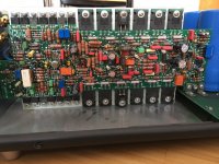
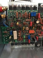
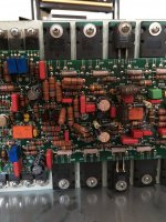
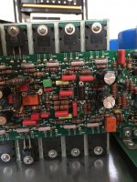
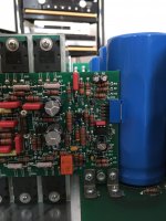
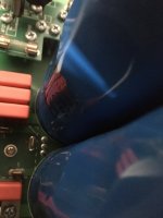
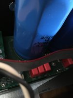
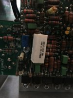
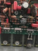
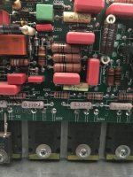
P.S: I attached some pictures of the PCB of one channel. Looks like someone played a bit with the AMP5 board and cramped all components on this compact PCB...Obviously the ML design looks more neat...but in terms of trace lengths this should be hard to beat...
luckily I found this thread and was able to learn a lot about my Proceed HPA2 and the ML 431/432. Thank you for sharing the schematics!
I compared the material for the HPAs and 431 and I can hardly find any differences (HPA: MPS8599; ML43x: MPSA56, HPA input buffer to compensate for the 6dB drop on RCA input, double capacitor size on ML431). The adaptive bias circuit seems a bit different (maybe just differently sketched). Do you expect any significant sonic differences between the HPA and the ML431?
I was a bit dissappointed to see a pretty basic regulation for the voltage gain stage based on LM317/337. In the past ML used a more sophisticated regulation for the higher powered versions e.g. 331 vs. 332/333 and 334 vs 335/336 (I saw the schematics for the 336 and still have to understand it...looks very complicated). Since this specific page of the ML432 schematics hasn't been shared (yet), could someone check if this model is also using LM317/337? Maybe there is some potential for adding such regulation to my HPA2
Would be great to also get your feedback on below questions:
- ML431 and HPA2 seem to be so similar but HPA spec seems superior (from data sheets, besides output power only one value for 431 and 432 provided). Why?
HPA: 250W@8Ohm, with no more than 0.1% THD, FR variation within 0.15dB ( all 20-20kHz), SNR better than -80dB (@1W)
ML431: 200W@8Ohm, with no more than 0.5% THD, FR variation within 0.3dB ( all 20-20kHz), SNR better than -65dB (@2.83V)
- I assume that the higher output power of HPA vs. 431 is because of a higher unregulated rail voltage, right? Then why is the idle power consumption of 431 2.5x the one of HPA (standby consumption for both ~100W, idle 150W (HPA2) vs. 375 (431))? Is this caused by a different adaptive bias scheme? How to see that from the schematics? I thought that the main advantage for adaptive bias is to limit the bias to the minimum level needed to keep "class A" operation load and signal dependent. Was the HPA level too optimistic so that they changed for the ML range?
Sorry for all the questions and thank you for your great support
Michael
P.S: I attached some pictures of the PCB of one channel. Looks like someone played a bit with the AMP5 board and cramped all components on this compact PCB...Obviously the ML design looks more neat...but in terms of trace lengths this should be hard to beat...
Attachments
-
 IMG_0933.JPG555.8 KB · Views: 209
 -
 IMG_0934.JPG512.3 KB · Views: 180
 -
 IMG_0935.JPG522.9 KB · Views: 155
 -
 IMG_0936.JPG506 KB · Views: 177
 -
 IMG_0937.JPG432.7 KB · Views: 171
 -
 IMG_0938.JPG380 KB · Views: 150
 -
 IMG_0939.JPG457.2 KB · Views: 135
 -
 IMG_0940.JPG313.5 KB · Views: 135
 -
 IMG_0941.JPG390.6 KB · Views: 139
 -
 IMG_0943.JPG548 KB · Views: 160
 -
 IMG_0944.JPG524.1 KB · Views: 185
Hi Michael,
indeed there is not so much difference between the HPA2 and the successor(s) ML431/432; ML obviously decided to produce two different amps, one with less and the other with more output power, the difference is mostly due to the different rail supply voltages and of course the different transformers.
I have had no HPA2 to compare with my 431, but I would not give too much attention to the different numbers in the specs; the audible difference is most probably very small. Much more important are the speakers, which should be able to handle peaks properly with small distortion.
best regards
Dieter
Hi Dieter,
thank you very much for your reply. I expect the same.
Nevertheless I am a bit puzzled how Madrigal transformed the HPAs into the Mark Levinson world: instead of adding them at a lower positioning they simple replaced their most popular amps (300 series, which was always marked as superior when Proceed was still active).
Looking at the response in diverse forums many people critizise the ML431/432 and many successors as "just" re-badged HPAs. On the other side this design "platform" seems to deliver better measuring performance (despite maybe pure current delivery) and simplified service (you start valuing that once you have a problem with your "artisian" products). Sorry for off-topic...
Anyway, it would be nice to know if the ML432 does also only feature the LM317/337 regulation. Maybe someone has the corresponding schematics or pictures to clarify.
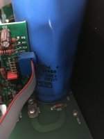
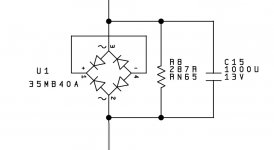
I have some temporary transformer hum (mechanical) with my HPA2 and saw something I interpret as a DC-filter circuit (s.pic) on the ML431/2 schemactics: a bridge rectifier with a capacitor and resistor in parallel. Is this correct? The capacitor seems to be a bit low in value (1000uF/13V) for such a high power amp. I could build something in a separate box but would like to get your feedback on the value and the necessary ripple current capabilities.
Thank you!
Michael
thank you very much for your reply. I expect the same.
Nevertheless I am a bit puzzled how Madrigal transformed the HPAs into the Mark Levinson world: instead of adding them at a lower positioning they simple replaced their most popular amps (300 series, which was always marked as superior when Proceed was still active).
Looking at the response in diverse forums many people critizise the ML431/432 and many successors as "just" re-badged HPAs. On the other side this design "platform" seems to deliver better measuring performance (despite maybe pure current delivery) and simplified service (you start valuing that once you have a problem with your "artisian" products). Sorry for off-topic...
Anyway, it would be nice to know if the ML432 does also only feature the LM317/337 regulation. Maybe someone has the corresponding schematics or pictures to clarify.
I have some temporary transformer hum (mechanical) with my HPA2 and saw something I interpret as a DC-filter circuit (s.pic) on the ML431/2 schemactics: a bridge rectifier with a capacitor and resistor in parallel. Is this correct? The capacitor seems to be a bit low in value (1000uF/13V) for such a high power amp. I could build something in a separate box but would like to get your feedback on the value and the necessary ripple current capabilities.
Thank you!
Michael
Attachments
dieter,Hi Symphony,
unfortunately I don't have any schematic of the 532 - sorry!
best regards
Dieter
Thanks for your answer!....do you know what the Bias setting is for the 431/432?......thanks!
Hi Symphony,
as discussed earlier in this thread it is 9 mV to be measured on one of the emitter resistors of the power stage transistors; 9mV over 0,22 Ohm result in 40mA idle current per power transistor. The trimpot R213 will adjust it.
you will find also the schematic earlier in this thread
best regards
Dieter
Hi Dieter, I'm having the same problem as you with my ML 431. Scratching noise in the left channel. I've gone over every solder joint on both left ch boards + adjusted all trimpots to match the ones on the right channel but still cannot get rid of the scratching/crackling noise. FYI, I did not find any suspicious solder joints either. Just curious if you've found anything in the circuit diagrams that has helped you with this problem? Thanks in advance. AndréHi there,
so, another year passed by and I was still not able to find a circuit diagram for the ML 431; I took both power amps out and after some solid resoldering (I did not see one suspicious solder joint) the scratching noise in the left channel is now on a very low level. The right channel is now completely scratch- and hiss free.
Does anybody got in between a circuit diagram of this ML431? Just in case when there may be a bigger problem??
best regards
Dieter
- Home
- Amplifiers
- Solid State
- Mark Levinson 431 schematics needed