Hi guys, I have this Marantz PM66 SE KI Signature that doesn't have a relay click when powered on. I experimented with test speakers and the output sounds fine if I manually push and hold the relay with a plastic stick.
Can anyone please help a beginner out with this one? The relay doesn't appear to be pitted.
Many thanks to anyone with the patience to help!
Can anyone please help a beginner out with this one? The relay doesn't appear to be pitted.
Many thanks to anyone with the patience to help!

There are 3x relays in the machine. They ALL use the +24V supply....I have this Marantz PM66 SE KI Signature that doesn't have a relay click when powered on.
Can anyone please help a beginner out with this one?
To test, press the 'SOURCE DIRECT' switch. You should hear a relay engage (click).
If you're unsure that you heard a relay click, insert a 6.3mm jack plug into the headphone socket. You'll hear the headphone relay engage (click) and the speaker relay disengage (if it's functional).
If you don't hear any relays click, the +24V supply is missing.
Good Luck!
Last edited:
Thanks for replying! When I press source direct I can hear the the left and right red relays clicking but the speaker relay does nothing. It plays fine on both channels if I take the cover off of the relay and push the contacts like this.If you don't hear any relays click, the +24V supply is missing.
Some years ago, many, mine failed with no sound.
I replaced a resistor and that was it. I think you should be able to find several threads from that time to identify which one it was.
If you don't get the answer in a day or two I will investigate further to see what i did way back then.
I replaced a resistor and that was it. I think you should be able to find several threads from that time to identify which one it was.
If you don't get the answer in a day or two I will investigate further to see what i did way back then.
Normally I would advise you to measure if there's any DC-voltage present on the input pins of the speaker relay - like rayma suggested - before doing anything else.Thanks for replying! When I press source direct I can hear the the left and right red relays clicking but the speaker relay does nothing. It plays fine on both channels if I take the cover off of the relay and push the contacts like this.
View attachment 1298803
That should be step one because manually closing the speaker relay when an output transistor would have gone short circuit to a power rail would probably fry your test speakers.
Please measure for that and report back.
In the meantime I have a question. I really don't like the look of the scratches and brown spots on the pcb near those big blue filter caps. Is that your doing or does this amp have a history before you got it?
Only 1x relay should click when the 'SOURCE DIRECT' switch is operated - it's on the input seelector PCB....When I press source direct I can hear the the left and right red relays clicking but the speaker relay does nothing.
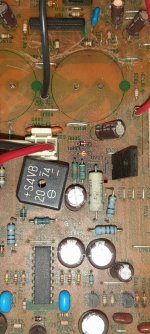
Measure the voltage between the heatsink and each end of DN03 (yellow box) and post the results.
And, as requested by other contributors, please provide the voltages on the centre pins of R767 & R768.
Good Luck!
I did look up what I did approx. 22-23 years ago to fix mine.
On either side of the diode bridge one of the 47 ohm 1/2 watt fusible resistors had gone Open Circuit, the board no's are R802 and R804.
R804 had failed in my case.
In fact r801-r804 and r807 are all listed as fusible in the manual. If still trying to track this particular fault down they might be worth a quick check with the DVM.
Normally I would advise you to measure if there's any DC-voltage present on the input pins of the speaker relay - like rayma suggested - before doing anything else.
That should be step one because manually closing the speaker relay when an output transistor would have gone short circuit to a power rail would probably fry your test speakers.
Please measure for that and report back.
In the meantime I have a question. I really don't like the look of the scratches and brown spots on the pcb near those big blue filter caps. Is that your doing or does this amp have a history before you got it?
Thank you so much for all the help.
The history is that the guy who owned it thought the volume pot was dodgy and the area of the board around both power caps was covered in that corrosive glue. When cleaning it off with isopropyl alcohol I scratched the board accidentally. I had a normal PM66 that's why the left cap is shorter. I swapped that one out.
I'll test the DC offset tomorrow but fairly certain it was 3 to 4mv area.
I did look up what I did approx. 22-23 years ago to fix mine.
On either side of the diode bridge one of the 47 ohm 1/2 watt fusible resistors had gone Open Circuit, the board no's are R802 and R804.
R804 had failed in my case.
In fact r801-r804 and r807 are all listed as fusible in the manual. If still trying to track this particular fault down they might be worth a quick check with the DVM.
Thanks for taking the time to help me with this one. I'll do the tests that the other guys suggested then look at the those fusible resistors. I actually don't think the headphones are working either.
That's what I suspected could be the case.Thank you so much for all the help.
The history is that the guy who owned it thought the volume pot was dodgy and the area of the board around both power caps was covered in that corrosive glue. When cleaning it off with isopropyl alcohol I scratched the board accidentally. I had a normal PM66 that's why the left cap is shorter. I swapped that one out.
I'll test the DC offset tomorrow but fairly certain it was 3 to 4mv area.
If the DC offset indeed turns out to be only a couple of mV, the speaker protection circuit should not keep the relays open, however, if that corrosive glue damaged the resisitors near those filter caps, it could be malfunctioning. That SIL chip probably is the TA7317 speaker protecion IC. Checking those components would be the next step.
Only 1x relay should click when the 'SOURCE DIRECT' switch is operated - it's on the input seelector PCB.
Measure the voltage between the heatsink and each end of DN03 (yellow box) and post the results.
View attachment 1298936
And, as requested by other contributors, please provide the voltages on the centre pins of R767 & R768.
View attachment 1298940
Good Luck!
Here's what I've noted so far today. 10.1mv on the center pin. DC offset was around 00.2mv. RN12 is open.
Attachments
That's a pretty common occurrence when the glue goes acidic and eats away that the components it touches.
I believe the main PCB is the same as the one that went into the PM-40SE I once had, of which I have the service manual.
If that resistor is designated as "RN12" on your PCB, then it's a 100k resistor that should go in there.
Putting "any resistor at hand" in could have blown up your circuit. Better turn off the amp now.
The colour coding of that resistor you put in reads to me as an odd value, whichever way around you read it. Either 1k1 or 151 Ohms, and both are way too low.
Edit: I found an abbreviated version of the service manual for the PM-66SE KI and it confirms RN12 to be a 100k resistor.
Attachments
Last edited:
That's a pretty common occurrence when the glue goes acidic and eats away that the components it touches.
I believe the main PCB is the same as the one that went into the PM-40SE I once had, of which I have the service manual.
If that resistor is designated as "RN12" on your PCB, then it's a 100k resistor that should go in there.
Putting "any resistor at hand" in could have blown up your circuit. Better turn off the amp now.
The colour coding of that resistor you put in reads to me as an odd value, whichever way around you read it. Either 1k1 or 151 Ohms, and both are way too low.
Edit: I found an abbreviated version of the service manual for the PM-66SE KI and it confirms RN12 to be a 100k resistor.
Thanks for that. I'll order in some the proper value.
- Home
- Amplifiers
- Solid State
- Marantz PM66 SE KI Signature No Output Unless Relay Held in Position? Help Please!