Re: cd63se please help
Its a simple fault mate!
If the headphones output both channels then the opamps in it are fine. The cds opamps feed the headphone opamp.
Chances are the track to the RCA socket is broken, check where you soldered it in for a break next to the pad.
Also what Simon said is correct about the resistor to take audio from to test.
Good luck")
Brent
Eggzy said:I got a MARANTZ CD63se from the car boot sale last week for a tenner!
The back analogue output sockets were dented in and the machine had some scratches hence the price. Upon opening I found the PCB seemed physically ok. I salvaged an identical RCA socket assembly from an old CD player which I duly soldered into place…the result was no sound from the left socket. Visually it all seems okay so I assume that at sometime some invisible damage has been done. I hooked the player up to an amp and using a probe attached to the + of the left socket I prodded some areas of the PCB near the socket hoping for a signal, sadly not a peep on the LH channel but the RH sounds fine.
However the front headphone output works fine so using an adaptor I fed my amp from the headphone socket but it sounded too loud & distorted.
I was thinking of wiring up the 3 point (R,G,L) headphone output to the rear RCA phono sockets via a series resistor. So I would like to ask; have I overlooked something or would this be a good solution? It’s too good to throw in the bin.
Any feedback would be greatly appreciated
Cheers J
Its a simple fault mate!
If the headphones output both channels then the opamps in it are fine. The cds opamps feed the headphone opamp.
Chances are the track to the RCA socket is broken, check where you soldered it in for a break next to the pad.
Also what Simon said is correct about the resistor to take audio from to test.
Good luck
Brent
Frequency on pin 9 BCKI 5.6448 Mhz?
Hi,
The BCKI input latches the data input (DI) into the Serial in parallel out (SIPO) shift register. Then the LRCI switches between left, and right registers.
"The timing of the arithmetic and output circuits is independent of the input circuits, isolating them from jitter or skew on the input clock circuits. As a result, phase differences between LRCI, BCKI, and XTI that may occur after a reset do not affect the correct operation of the device. However, the correct frequency ratio between LRCI, and XTI should be maintained." p20, SM5872 datasheet.
As I understand it there are two independent clock sections (one input section, and one output clocking section).
What's the frequency on pin 9 BCKI ?
-is the frequency 5.6448 Mhz ?
Does it matter if the BCK is jittery ?
Is there any value in reclocking LRCI ?
Re: RE. Ultranalog SACD enhancer
Hi Andy,
That was a few weeks ago, starting somewhere around here.
I am building a second version now, with FET's. I also tried the darlington setup, I used a BC517, works fine.
I made a new version of the schematics, with parts & placement:
Regards,
Ray.
poynton said:Hi.
Ray,
Have you played around with this circuit, at all ?
I was thinking in particular of the following :-
Replacing the output pair with a darlington transistor eg. 2N6426
Replacing the CCS pair with a CCS diode or FET
Basically to reduce the component count.
Andy
Hi Andy,
That was a few weeks ago, starting somewhere around here.
I am building a second version now, with FET's. I also tried the darlington setup, I used a BC517, works fine.
I made a new version of the schematics, with parts & placement:
Regards,
Ray.
Attachments
Re: Re: RE. Ultranalog SACD enhancer
6h5c said:
That was a few weeks ago.............[?QUOTE]
How time flies when your having fun !
I made a new version of the schematics, with parts & placement:
Hi Ray,
I cannot find the schematic. Is it in the zip file?
Andy
Re: Re: Re: RE. Ultranalog SACD enhancer
Hi Andy,
Yes, it's supposed to be....
I created a Word document with OpenOffice, because the PDF was too big to post. I hope it opens correctly, just let me know if it isn't compatible and i'll try something else.
Regards,
Ray.
poynton said:Hi Ray,
I cannot find the schematic. Is it in the zip file?
Andy
Hi Andy,
Yes, it's supposed to be....
I created a Word document with OpenOffice, because the PDF was too big to post. I hope it opens correctly, just let me know if it isn't compatible and i'll try something else.
Regards,
Ray.
Re: Re: Re: Re: RE. Ultranalog SACD enhancer
Hi just the parts and placement lists
At the top are 2 page breaks
Andy
6h5c said:
Hi Andy,
Yes, it's supposed to be....
I created a Word document with OpenOffice, because the PDF was too big to post. I hope it opens correctly, just let me know if it isn't compatible and i'll try something else.
Regards,
Ray.
Hi just the parts and placement lists
At the top are 2 page breaks
Andy
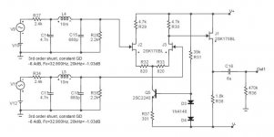
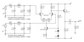
Both of them are basically the passive filter part followed by a stage based on the Ultranalog SACD Enhancer.
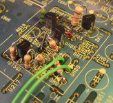
I adjusted the amplification a bit, to get 2V rms output. I use the original current sink of the HDAM circuit, and it's possible to get all the components on the PCB. Here's a pic of the latest FET version:
Regards,
Ray.
I adjusted the amplification a bit, to get 2V rms output. I use the original current sink of the HDAM circuit, and it's possible to get all the components on the PCB. Here's a pic of the latest FET version:
Regards,
Ray.
Attachments
Re: forum-mail
Hi Elso,
Didn't get your mail, when did you send it?
Here's the schematic & board I made. It's based on your clock, only with single supply, and Guido's XO-supply.
Regards,
Ray.
Elso Kwak said:Hi Ray, Care to share the schematic of your version of the KWAK-CLOCK?
Did you receive my mail?
Regards,
Hi Elso,
Didn't get your mail, when did you send it?
Here's the schematic & board I made. It's based on your clock, only with single supply, and Guido's XO-supply.
Regards,
Ray.
Attachments
Re: Re: forum-mail
Very nice, Ray !
Home produced ?
Group buy ?
Andy
6h5c said:
Here's the schematic & board I made. It's based on your clock, only with single supply, and Guido's XO-supply.
Very nice, Ray !
Home produced ?
Group buy ?
Andy
Re: Re: Re: Re: forum-mail
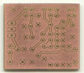
Thanks Andy! Yes, it is home-made. I used Eagle.
I also etched me some PCB's.
Why? As long as it's not commercial....
Ray.
poynton said:Very nice, Ray !
Home produced ?
Group buy ?
Andy
Thanks Andy! Yes, it is home-made. I used Eagle.
I also etched me some PCB's.
Elso Kwak said:I object!

Why? As long as it's not commercial....
Ray.
Attachments
Re: Re: Re: Re: Re: forum-mail
Any way, Ray, your clock is nothing like KC7.
KC& has dual supplies.
The comparator is connected to the oscillator via a cap. in KC7.
He obviously wants to claim credit for every oscillator / comparator clock !
I got a nasty personnal email from him !
Andy
6h5c said:
Why? As long as it's not commercial....
Ray.
Any way, Ray, your clock is nothing like KC7.
KC& has dual supplies.
The comparator is connected to the oscillator via a cap. in KC7.
He obviously wants to claim credit for every oscillator / comparator clock !
I got a nasty personnal email from him !
Andy
Re: clock
And I don't even claim it is mine, I just threw the parts on a board....
Did he threaten you?
Now i'm seriously considering editing the "thanks to..." line in the PDF.
Ray.
poynton said:Any way, Ray, your clock is nothing like KC7.
And I don't even claim it is mine, I just threw the parts on a board....
I got a nasty personnal email from him !
Andy
Did he threaten you?
Now i'm seriously considering editing the "thanks to..." line in the PDF.
Ray.
very nice work Ray
I've been using the tent XO module with a his psu (psu home made).
passive filter(4,7mH version) and the bc550c buffer(filter and buffer on home made pcb)
Was thinking about using HDAM circuit but pain in a** to remove pcb to vary anything.
just this weekend started doing extra power supplies.
didn't want to disrupt it, just sounds very good
Much difference between fet and transistor?
allan
"And I don't even claim it is mine, I just threw the parts on a board...."
Lucky throw that was! I don't think it would happen to me
I've just finished installing 2 LT340's for the DAC and soldering the 220nF capacitors on my dil8 sockets (with AD827)...
It's interesting what difference those two changes made (although I already had a regulator installed on one of the two powersupplies to the DAC).
But since my last mods didn't make that much of a difference (changing some capacitors near the servo), I was foolish enough to do these two changes at the same time.
The results: the ultralow bass has lessened, which I considere a good thing since I live in a concrete building which has a tendency to emphasise these frequencies. But the extreme high frequencies are very audible on 'kind of blue' (by you know who), it is also like the whole band has taken a step backwards. Although the background noise in these recordings now is immediatly noticable. Switching back to my 'extreme high' testing CD (with a hoarse female voice), I first of all noticed the accoustic guitar is less pronounced and unfortunately has a tendency of getting a bit lost in the sound of the cello.
I'm afraid I soon will remove the 220nF's at the opamps just to see what changes they make (but not after making a quick switch to lm6172's).
I'm such a happy tweaker! Now I can listen to all my cd's all over again
Thanks everybody
regards,
Jacco
- Home
- Source & Line
- Digital Source
- Marantz CD63 & CD67 mods list