Thanks Ray, much appreciated. One last question on that subject, and sorry if this is obvious or has been covered in great detail a gazillion times already: If I do still find that I have a significant DC offset and decide to put the Mundorfs in, do I still need the resistor and should I put it before or after the caps?
The CD67's servo is integrated in the decoder-chip. This get's the clock from The Flea as well, so the servo is clocked by The Flea indirectly.
In a CD63 the servo is a separate chip, you can use The Flea to replace the original resonator. You need a 8.467MHz XO for that.
Ray
Thank you Ray
I am using two C1 clocks in my 53... Would I notice improvements replacing those by two Fleas ?
Thanks Ray, much appreciated. One last question on that subject, and sorry if this is obvious or has been covered in great detail a gazillion times already: If I do still find that I have a significant DC offset and decide to put the Mundorfs in, do I still need the resistor and should I put it before or after the caps?
Yes, the resistor should stay. The coupling cap is transparent for AC signals, so the opamp 'sees' the same load at it's output. It doesn't matter whether you put it before or after the cap.
The best solution would be to lose the output cap; the best cap is no cap
 .
.If the offset is too high and you already put 1% (or better) resistors in the analog filter, you could also cancel the offset by appying a small DC voltage to pins 5 of the opamps, where the 22k resistor is. Use a 1k or 2k trimmer and tie the wiper to pin 5. Tie the ends of the trimmer to + and -12V through a 100...220k resistor and you will be able to trim away any offset very accurately. Once the needed voltage is known, you may even replace the trimmer by a fixed resistor.
Regards,
Ray
Thank you Ray
I am using two C1 clocks in my 53... Would I notice improvements replacing those by two Fleas ?
Yes, I would expect so. I would start with the DAC clock. I don't know the numbers for the C1, but the Flea's on-board supply is very low-noise. Also, if you use the Tentlabs XO you'll have an oscillator that's true low-jitter. You may also fit the original C1 oscillator on the Flea board, as it accepts an SMD oscillator, but I don't know the jitter specs for this type (Brent?).
What's really important is that you use separate power supplies and don't power the clock off the player's board.
Regards,
Ray
I am using a dedicated PSU for the clocks. But I always wondered about the differences on the oscilators.
I am using a dedicated PSU for the clocks. But I always wondered about the differences on the oscilators.
The oscillator is the main component that has to have the lowest jitter possible of course. But if it is fed with a noisy supply, the noise will partially penetrate into the signal, and cause jitter. So a healthy supply is equally important
Ray
Hi guys,
I'm gonna try and regulate the Servo drivers on a 63KI.
It looks like I want -12v to pin 9 and +12v to pin 2 on Q105 and Q106. Am I right?
What does QM 01 do and is it worth regulating.
Thanks
Steve
Hi Steve,
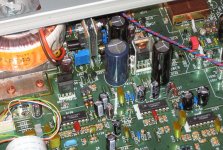
+/-12V is a bit too high. You won't break anything, because the drivers can handle 40V, but the motors don't need such a high voltage. The voltages that are listed in the service manual are measured at no load in STOP mode. When the player is working, it's more like 9...10V or so, depending on the size of the buffer caps C813/C814. You can use standard 7808/7908 regulators if the voltage under load is at least 10V. They need about 2V voltage difference between input and output. If you enlarge the two buffer caps you can crank this up a little if it's a bit too low. If you use an external supply, this doesn't apply of course
.In my CD63-KI I used LM317/337 regulators and tuned the output voltage with a trimmer to about +/- 7.5V and used my scope to check if there weren't any dips in the output, works equally well! I used only two regulators for all drivers and put them where R149/R150 are. I moved C852 to the back of the board to make room. U161 and U162 were removed to disconnect QM01 and Q105 and I wired them to the new regulators under the board.
Here's a pic!
Regards,
Ray
Attachments
Thanks Ray,
seems simple enough
I assume pins 2 and 9 are correct
seems simple enough
I assume pins 2 and 9 are correct
Hi Steve,
+/-12V is a bit too high. You won't break anything, because the drivers can handle 40V, but the motors don't need such a high voltage. The voltages that are listed in the service manual are measured at no load in STOP mode. When the player is working, it's more like 9...10V or so, depending on the size of the buffer caps C813/C814. You can use standard 7808/7908 regulators if the voltage under load is at least 10V. They need about 2V voltage difference between input and output. If you enlarge the two buffer caps you can crank this up a little if it's a bit too low. If you use an external supply, this doesn't apply of course
In my CD63-KI I used LM317/337 regulators and tuned the output voltage with a trimmer to about +/- 7.5V and used my scope to check if there weren't any dips in the output, works equally well! I used only two regulators for all drivers and put them where R149/R150 are. I moved C852 to the back of the board to make room. U161 and U162 were removed to disconnect QM01 and Q105 and I wired them to the new regulators under the board.
Here's a pic!
Regards,
Ray
Yep, pin 2 is +. Pins 4 and 9 thru 16 are tied together and are -.
Ray
Thanks
Hi guys, I bypassed my HDAMs this weekend, wiring directly from R617/18. I'm pretty happy with it overall. It's the first mod I've done that has given me the impression of a trade-off of positive qualities rather than just pure gains ('thrilling wallop' vs 'musical goods'?). The volume is lower and some of the punchiness has gone out of it, but there is more detail and it sounds more balanced. I suppose my player is growing up <sniff>
I noticed last night that if I turn the volume up right up while the player is stopped, there is now some very faint noise where previously there was dead silence. It sounds partly digital in origin, i.e. has a sort of distant modem-like quality. Is this normal? Have I just bypassed muting? Is this the dreaded noise demon that I must now fight with regulation and rail separation? Or did I just mess something up?
Edit: I should mention that this noise is quieter than the low level background noise from my turntable, and is not remotely audible at normal listening levels.
Last edited:
Cool!
The trade-off effect is normal in the beginning, if the player is not fully tweaked some changes can have a moderate or even negative effect. Mine sounded awful in the beginning without the HDAM. Only after I sorted out the opamp supply and the analog filters, the opamps started to sing. Some of the punch will come back with upgraded power supplies.
The noise is indeed residual noise from the DAC, which is normally muted by the muting transistors in STOP mode. But it's right back at PLAY but masked by the music. Did you notice it before the HDAM bypass? It should not have changed due to the bypass.
Regards,
Ray
The trade-off effect is normal in the beginning, if the player is not fully tweaked some changes can have a moderate or even negative effect. Mine sounded awful in the beginning without the HDAM. Only after I sorted out the opamp supply and the analog filters, the opamps started to sing
. Some of the punch will come back with upgraded power supplies.The noise is indeed residual noise from the DAC, which is normally muted by the muting transistors in STOP mode. But it's right back at PLAY but masked by the music. Did you notice it before the HDAM bypass? It should not have changed due to the bypass.
Regards,
Ray
Hi Ray, that's good news. It doesn't sound awful at all. I've already done some PSU changes. I have up-rated Black Gates pretty much everywhere except for C803/04/13, which are Mundorf AG 22,000uF. I imagine that they in particular have probably saved me from a noticeable drop in bass. I have also used 1% silver mica in the analogue filter. The noise is only audible at speaker-destroying levels but I think I might've heard it when playing a silence track on a test CD once before. I don't think it's probably changed at all.
Ok, so the player is far from standard now . The Black Gates are nice!
I still had the original opamps in there when I did the bypass. Not recommended . I quickly swapped it for an AD827 and replaced the standard resistors and caps with close tolerance resistors and polystyrenes. That gave me more detail, a better soundstage and less offset at the output. I settled for the AD8610 in the end and that's still my favorite opamp.
Regards,
Ray
. The Black Gates are nice!I still had the original opamps in there when I did the bypass. Not recommended
. I quickly swapped it for an AD827 and replaced the standard resistors and caps with close tolerance resistors and polystyrenes. That gave me more detail, a better soundstage and less offset at the output. I settled for the AD8610 in the end and that's still my favorite opamp.Regards,
Ray
Here is my CD67 KI. I ended up with a fault on the CD63 board that I couldn't resolve, so had to use the board from a spare CD67. Notable mods include:
- KI toroid fitted in place of original CD67 transformer
- Additional 30VA toroid for 5V regs
- Additional 30VA toroid for 12/-12 reg
- Chassis and transport dampening
- 5v "Q-mini" reg dedicated to DAC
- 5v "Q-mini" reg for decoder and 1ppm TCXO
- 1ppm TCXO for DAC
- 5v "Q-mini" reg dedicated to servo
- 12/-12v "Q-mini" reg for analogue stages
- Os-cons on digital supply lines
- Silmics on analogue supply lines (HDAM and op-amps)
- OP627 op-amps
- 10uF Wima MKS-4 output caps
- New phono sockets
Pics:
Pic 1
Pic 2
I am tempted to take this further, but I guess I'm at around 80% of what this player is capable of and might only get small gains if I continue. I am very happy with the sound, it is much cleaner in the midrange and treble than the standard KI (before I ruined the CD63 board), and dynamics and leading edges are far more apparent.
I have a Marantz CD65 MkII winging its way to me which will get a very similar level of treatment. This player uses the TDA1541A DAC.
Last edited:
- Home
- Source & Line
- Digital Source
- Marantz CD63 & CD67 mods list