
Whoa! He's got a guide I have been after for ages - Guinea pig guides on eBay (end time 23-Feb-11 16:35:23 GMT)
LMAO
Brent
LMAO
Brent
Maybe they are the ultimate upgrade ??
Guinea-pig power!
But how would you get rid of the squeeks in the mechanism ?
Also on Fleabay -- http://cgi.ebay.co.uk/Marantz-CD-63...dioHiFi_CDPlayerSeparates&hash=item2c5ad3d275
andy
Still in the Seychelles. Only another 5 weeks to go !
Guinea-pig power!
But how would you get rid of the squeeks in the mechanism ?
Also on Fleabay -- http://cgi.ebay.co.uk/Marantz-CD-63...dioHiFi_CDPlayerSeparates&hash=item2c5ad3d275
andy
Still in the Seychelles. Only another 5 weeks to go !
Last edited:
This is what the regulators look like fitted. This is before really big caps were fitted and the horrid green wire is gnd! Also in the photo is the clock coax feed to the servo which helps lots too!
With respect to the fuses, the only downside to shorting them out (linking them out under the PCB) is that if you make a mistake while further modding anything on the 5v rail, you could do damage to the PSU componets or transformer winding. Personally, I'd leave it till last!
Thanks for the pics and advice
")
I was wondering, are there many more mods than described on Ray's website? I'm also not sure if all the mods are worth doing. There seem to be some crazy extreme audiophile mods that won't actually make a difference, like the bitumen pads.
There seem to be some crazy extreme audiophile mods that won't actually make a difference, like the bitumen pads.


Couldn't help it That's what happens if you hang around here. Actually the bitumen tweak is easy-peasy and works. It dampens the cheap ringy casework. costs about a pound if you can find a single sheet at an auto supply store. It's a dog's diner to get off so make sure you get it right first time.
That's what happens if you hang around here. Actually the bitumen tweak is easy-peasy and works. It dampens the cheap ringy casework. costs about a pound if you can find a single sheet at an auto supply store. It's a dog's diner to get off so make sure you get it right first time.Well the effects are cumulative. Each little bit enhances or underpins the others. It doesn't hurt to try? At the end of the day (whenever that is) you have several degrees of satisfaction; better sound being one and the other is having engaged with the machine in an intimate way. I don't know how else to say it! like you can buy anything off the shelf but you get into another head space when you know you have groped around inside (so to speak) I guess I better leave it at this. Your choice.
Yeh, buy some 7808 and 7908 regulators (3 of each) and tap power from the +-10V rails that previously supplied the servo drivers to supply each chip (there's a resistor on each supply you can lift to isolate it) with its own regulated rail. Have a good gander at the service manual and come back with any questions.
The fuse only protects one part of the player and it's the most power-hungry part which, particularly in vanilla-grade models, is supplied with a barely-adequate supply. The fuse is resistive so it's just a little tweek to lift the ability of the supply.
Okay, I had a good look at the service manual and I'm left with a few questions:
What to do with the resistors? Do I replace them with the regs or do I add the regs parallel with the resistors?
Also, on UV101's picture I see there are 2 regulators in place of jumpers U149 and U150. I couldn't find these jumpers in the schematic. I did find R149 and R150 which are connected to the power rails, but I can't find these resistors on the PCB... So is it correct to replace jumpers U149 and U150 with regulators?
Thanks brent,I do bang on about this a lot but C813 needs swapping for a massive uF cap (10000uF min) we use 22000uF + short the fuses out. Bass is improved along with the whole sound
Brent
RS do a panasonic 22,000 uf 25v that do the trick then short the fuse holders .
cheer alan.
ps copper bar you know where
Alan those panasonics are very good vfm
Panasonic 22,000uF 16v
Get 2 and do the C814 as well!!! they are only.
If you really feel like pushing the boat out, get 2 of these for the other rails and replace C803 and C804
Panasonic 22,000uF 25v
You will need to be creative with placement but it'll be time and money well spent if you ask me!
Panasonic 22,000uF 16v
Get 2 and do the C814 as well!!! they are only.
If you really feel like pushing the boat out, get 2 of these for the other rails and replace C803 and C804
Panasonic 22,000uF 25v
You will need to be creative with placement but it'll be time and money well spent if you ask me!
Last edited:
Okay, I had a good look at the service manual and I'm left with a few questions:
What to do with the resistors? Do I replace them with the regs or do I add the regs parallel with the resistors?
Also, on UV101's picture I see there are 2 regulators in place of jumpers U149 and U150. I couldn't find these jumpers in the schematic. I did find R149 and R150 which are connected to the power rails, but I can't find these resistors on the PCB... So is it correct to replace jumpers U149 and U150 with regulators?
My pal has my player at the moment so I cant check but the mod is to basically look for the rails to each of the driver IC's. You need to trace to a point that you can disconnect its own individual supply. From memory, 2 of the driver ic's have resistors in the supply's and one doesn;t (even tho it is shown in the SM).
All I did was to remove the supply resistor or link and put the supply pin of the reg into the supply side and the output side to the the driver ic side. Then you can solder the gnd pin directly to top of the board which is gnd.
Not sure if this will help or confuse!!!!
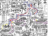
Red lines are the +10v supply, the red dots are where I connected the "in" pin of the 7808 reg. The purple lines are the regulator +8v output to the driver ic. The gnd pin of the regulator is connected to the screen layer on the top of the pcb.
The Blue lines are the -10v supply and the blue dots are where I connected the "in" pin of the 7908 reg. The yellow lines are the regulator -8v output to the driver ic. The gnd pin of the regulator is connected to the screen layer on the top of the pcb.
The 2 resistors at the top of the pic should be removed and linked out.
If you are doing all this, you should also change the local decoupling caps for rubycon ZLG 220uF or 470uf which I didn't do!!!
C153,154 C135,136 & C146148 (not sure about the last 2)
Edit last 2 are ceramic - replace with the ZLG and remove the other 4 ceramics that bypass the new ZLG's
Attachments
Last edited:
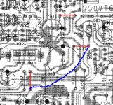
There is also the single 7808/7908, using the old pics ( courtesy of someone around, Andy ? ).
Fit them instead of the wire jumpers, remove the third one and put a wire to get the regulated DC there. And yes weak PSU players like my CD43 are at pain with this mod, calling for a new TX. BTW a cheap and effective mod!
Fit them instead of the wire jumpers, remove the third one and put a wire to get the regulated DC there. And yes weak PSU players like my CD43 are at pain with this mod, calling for a new TX. BTW a cheap and effective mod!
Attachments
Thanks,Alan those panasonics are very good vfm
Panasonic 22,000uF 16v
Get 2 and do the C814 as well!!! they are only.
If you really feel like pushing the boat out, get 2 of these for the other rails and replace C803 and C804
Panasonic 22,000uF 25v
You will need to be creative with placement but it'll be time and money well spent if you ask me!
get me 4 of those rs birmingham mon am tho
copyied rays hdam bypass to the tee what a disapointment i was expecting miracles didnt happen so i hope what you and brent say is all good put some genuine lm4562s in my cd52 se tonight sounds very good what a warm player that one runs rings round the 63 @ the mo.thanks alan
- Home
- Source & Line
- Digital Source
- Marantz CD63 & CD67 mods list