Hi Glenn,
"I should also point out that in my case the clock has its own mains transformer so is galvanically isolated from the rest of the player. I don't know if this is the case with yours."
Please.....I'm not trying to argue here....my intention is only to improve the sound......just a suggestion.
But we must connect the supply ground together to establish ground, the output of the clock current return must come back someway to the clock, and if you remove the shield ground on one point it will go a very long way via the supply ground, along with all it's ground bounce along the way, and with significantly more inductance on the path.
the only way to achieve galvanic isolation is to use pulse transformer or optical isolation.
Cheers,
Hartono
In my case I have Tent's transfomer and X02 board, with coax feeding the DAC. This takes clock signal to DAC and ground return via shield. I was told that if I take another wire to the decoder, the return path for the decoder's clock input would also be through the shield of the DAC feed. (Presumably modulating the ground potential at the DAC clock input.) This much is obvious I suppose. If both connections were gounded then I would have two return paths for the two signals.
The upshot being that it was better to have one connection to the DAC only, keeping this clean where it matters most, and let the DAC buffer it on to the decoder.
As I said, I don't know if this is absolutely correct or if I understood the advice correctly, but I just thought I should clarify it as I understood it.
Having said all that, my X02 has three outputs, and Guido must have put them there for a reason!
Hartono said:Hi Glenn2,
Yes this digital grounding can get pretty complicated......
Also I think it's very nice of you to put your suggestion here

Hartono
I suppose it's easy to try it out!
")
I also have those two unused clock outs from the tent X02 calling out for a connection to something!
My current x02 clock out is to dac pin 28 via jumper u196 less than a centimeter of trace away. The ground is to the plane under the dac at cd05 1/2 cm away. So far so good...but:
1. Why not use another x02 clock-out to the decoder using coax (+ and -) and eliminate another 5cm of trace and it's ground bounce? .Does the clock need to pass through dac before decoder?
2. My nicely designed tent reg that feeds the tent crystal would be a cleaner 5v for the dac clock section at pin 27. Is there a problem with that? Marantz seemed to think that one reg for all 5v was ok!
3. Taking that idea one step further, can't the same 5v reg also feed digital +5v at pin 16 of the dac? (same IC and not affecting the analog section.)
Really, I have read most of this thread, but it reminds me of that movie where the guy is about to pick up a huge real diamond and somebody throughs down a handful of fakes..the real gem is effectively gone!
Luckily there are some great gemologists on this forum to help!
Thanks!
ps- I'm about to wire up ALW/Martin's 317at reg to the dac analog at jumper 199 feeding the 4 analog +5v on the dac. I need a sense ground and a load ground...but left and right load grounds currently are not tied together until close to the cdp output! Suggestions needed!
After reading this regarding grounds from tentlabs.com, maybe I should just tie analog outs from dac (pins 19 and 24) to the ground plane under the dac? Now they don't tie to the ground plane until 10cm later, next to the RCA output jacks. It seems the designers had a reason, but...
My question about two grounds for the 5v reg still stands! I'm about to say screw it and tie them together like I didn't know better!

Guido Tent:
ICs with more than one supply / ground pin
If an IC has more supply pins, every pin must be connected following the same strategy.
If an IC has more then one ground pin, for example an analogue and a digital ground, all must
be connected directly to the first ground layer on the PCB, beneath the IC.
My question about two grounds for the 5v reg still stands! I'm about to say screw it and tie them together like I didn't know better!
My question about two grounds for the 5v reg still stands! I'm about to say screw it and tie them together like I didn't know better!
How about two regs? One for left and one for right. That's what I did. I had to cut a track to separate them.
I have an input wire to the middle track, decoupling grounds soldered to ground plane, output and adjust grounds to dac pins.
If you're just having the one reg, I'd suggest just connecting both grounds (decoupling and sense) together and to the ground plane. The load is still decoupled to the analogue grounds at the DAC itself.
Attachments
Joe-HT said:2. My nicely designed tent reg that feeds the tent crystal would be a cleaner 5v for the dac clock section at pin 27.
I wondered about this before. I assume you mean running the DAC's in-built clock buffer (pin 27) from the same +5V that the goes into the XO can.
I think I asked it on here once and somebody (maybe Martin) suggested it was a bad idea so I left it as it is.
I also asked Guido who suggested that as the extra noise would be 'synchronous' it would probably be OK to do this.
Faced with two opposing views I opted to leave it alone!
SimontY said:Nice Glenn. Looks like a good camera too
Only a compact, but a pretty decent one. Fuji F30.
As with all these things it what you do with it that counts.
(Indoor lighting, flash off, manual white balance, manual ISO, aperture priority, self-timer, camera resting on table.)
Sorry Glenn, I think it might be a good thing to feed the decoder with a seperate clock.
Firstly, the reason for doing it, the chance (however large or small it may be - I guess that's the major question) of the DAC and digital filter chip adding jitter to the clock signal as it repeats it on to the decoder is eliminated.
Secondly, I do see your concern with groundloops. However, for you could just use coax and only ground the shield at the decoder end.
As long as the clocks arriving at the decoder and digital filter&DAC
are the same, it should be fine to not pass the clock signal through.
I had a player that I have now stripped down as a transport, before I deactivated the rest of the circuitry I fed a seperate clock module to just the decoder, and the DAC and digital filter (before they were disabled) were running off their original clock signal, and they still worked fine (surprisingly - as they were off a different clock), but I wouldn't recommend doing that though. Point is, it should be okay - and there's no harm trying.
Cheers,
Phil
Cheers Phil,
Kinda makes sense.
If there is only one clock ground (at the DAC) this must carry the return current for the decoder clock feed too. I understood that the extra current flowing in this ground would dirty it and increase jitter at the DAC.... but maybe I got the wrong end of the stick.
Maybe a bit of extra noise or whatever at the DAC is worse than a bit extra at the decoder?
I dunno - maybe I'll try it out.
Glenn
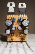
Now I see why you are called glenn2 (two in one!) Nice.
I think I'll copy that, although I do have a few green LEDs to put in, thanks Martin. (...1/5 to 1/8 of the noise!)
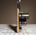
Where exactly are you attaching those nicely spaced legs?
BTW- With the board out and no power, I'm getting 0 ohms between u199 (+5v analog at dac) and ground plane. Is that normal? It seems like a short, but I never checked it before...
ps- Due to me being in asia, there is a 1/2 day lag here, thanks for following up. Additionally, I'm off for two days of volunteeer community service, but I'll be back!
Thanks for the help! I'll try coax (both leads) on the decoder clock from the x02 since it has extra clock out + and -. Trusting Guido on that one, guess he doesn't visit here anymore.
I think I'll copy that, although I do have a few green LEDs to put in, thanks Martin. (...1/5 to 1/8 of the noise!)
Where exactly are you attaching those nicely spaced legs?
BTW- With the board out and no power, I'm getting 0 ohms between u199 (+5v analog at dac) and ground plane. Is that normal? It seems like a short, but I never checked it before...
ps- Due to me being in asia, there is a 1/2 day lag here, thanks for following up. Additionally, I'm off for two days of volunteeer community service, but I'll be back!
Thanks for the help! I'll try coax (both leads) on the decoder clock from the x02 since it has extra clock out + and -. Trusting Guido on that one, guess he doesn't visit here anymore.
Hi Glenn,
I could be mistaken, and could be wrong, but in these circumstances, the coax feeding the clock is used for shielding, not as a transmission line, so as long as the shield is grounded, its doing its job.
You shouldn't need to return current through it.
As long as the ground is shared somewhere, you shouldn't have any problems IMO.
For my clocks, except once, I've always just used twisted pair (because I had some, and its easier to work with).
You could maybe do some star earthing or something with these shields.
Anyway, that's my take on the issue, and I could well be wrong, so what we need now is someone who can put us right on the subect.
Cheers,
Phil
Joe-HT said:Where exactly are you attaching those nicely spaced legs?
Well you may have to mount it sideways to right of the DAC. I mounted it between where the op-amps used to be (where the decoupling caps were) as I have removed the analogue stage and replaced it with an LC Audio Zapfilter2.
You could just put four in a row, for your four DAC supplies.
- Home
- Source & Line
- Digital Source
- Marantz CD63 & CD67 mods list