Hi,
0.3V would be 300mV, and that's a bit high. I doubt the measurement is correct, because I've never seen such high offset (unless there's something wrong).
It's better to measure directly at the opamps' output, because the muting transistors will clamp the voltage to ground (if still in there). It's fine if the player is in STOP mode this way.
The outputs are at pin 7, or U210 and U214 for CD63, U216 and U217 for CD67.
Thanks, Ray. I will pop the lid and measure again, this time at U210 and U214 later on and post my findings.
Thanks, Ray. I will pop the lid and measure again, this time at U210 and U214 later on and post my findings.
Duh!!! Sorry, correction, my measurement was .030V (i.e 30mv) and not .30V. I got the decimal point in the wrong place! Shows how dangerous I am!
But I will measure again later where you suggested and post the results.
Hi,
0.3V would be 300mV, and that's a bit high. I doubt the measurement is correct, because I've never seen such high offset (unless there's something wrong).
It's better to measure directly at the opamps' output, because the muting transistors will clamp the voltage to ground (if still in there). It's fine if the player is in STOP mode this way.
The outputs are at pin 7, or U210 and U214 for CD63, U216 and U217 for CD67.
I have a 63 and have measured at U210 and U214 and get exactly 0.030V DC for each. What would you suggest, a 2.2uF or 4.7uF blocking cap for each? Alternatively, given such low values, are blocking caps actually required? Also, will fitting of DC blocking caps make an audibly discernible difference or is their primary benefit in amp protection?
Sorry for the questions!
Any cap in series with the signal path will degrade sound quality, so it's best to use as few of them as possible. If your amp has a blocking cap at the input (most of them do) then you don't need one in your player. But you should check to be sure. 30mV is not high, but you can lower the DC offset further by using tight-tolerance resistors in the opamp filter, or use a trimming-circuit with a multi-turn trimpot.
If you are planning to build a DOS in the future, you do need a blocking cap anyway, as the DOS puts out a high amount of DC voltage because of the single-ended design. If you use a good quality MKP cap, the impact of the sound will be minimal. In that case it may be wise to invest in good caps in advance. If you use a mediocre electrolytic, you'll hear the difference")
Values between 2.2 and 4.7uF are fine, larger won't hurt.
Ray
If you are planning to build a DOS in the future, you do need a blocking cap anyway, as the DOS puts out a high amount of DC voltage because of the single-ended design. If you use a good quality MKP cap, the impact of the sound will be minimal. In that case it may be wise to invest in good caps in advance. If you use a mediocre electrolytic, you'll hear the difference
Values between 2.2 and 4.7uF are fine, larger won't hurt.
Ray
Last edited:
Any cap in series with the signal path will degrade sound quality, so it's best to use as few of them as possible. If you amp has a blocking cap at the input (most of them do) them you don't need one in your player. But you should check to be sure.
If you are planning to build a DOS in the future, you do need a blocking cap, as the DOS puts out a high amount of DC voltage because of the single-ended design. If you use a good quality MKP cap, the impact of the sound will be minimal. If you use a mediocre electrolytic, you'll hear the difference
Ray
Many thanks, Ray. Yes, I will be using a DOS (nearly completed), and from what you say, the DC voltage may well increase. So I will measure DC voltages again when I have set up the DOS.
I will also investigate whether my amp has a blocking cap at the input.
Hi guys,i know that this question is off topic but i did search the web for answers and apart from lampizator site...nothing else.I have a Cambridge CD-3 player and i want to change the op-amps.Now it has 1 5534 or 5334 per chanell,i can't see well there,and because it has 4 x tda 1541,so there are 8 op-amps.The sound of this player is amazing as it is...but after i did change the op amps on the cd63 to lm4562 and did listen to the huge difference they did instead of the 2114....i say why not change them on the CD-3 too.It's not as easy as the 63 to change them....and i wonder if it will be worth it.Also considering of changing diodes 1N4004 to MBR1100.Any suggestions?
And by the way,i search for a service manual for Camridge and the results are 0000!!!!!
Thanasis.
And by the way,i search for a service manual for Camridge and the results are 0000!!!!!
Thanasis.
Hi Guys,
I posted a while ago with a few questions about modding my CD67-SE. In the end I followed Ray's updated guides (on his site) and looked at posts on the this thread to help me work out stuff I didn't know about.
I've managed to complete most of the mods without any issues and the player sounds great. However I've got some outstanding points if you can help me answer.
1. Ray's guide says remove and wire jumper C655 - 658 - have you done this on your system? Do you recommend it?
2. C611 - 614 are red coloured Elna cerafines (100u/25v). The guide says replace with 220u/16v. The ones I ordered of at the recommended value were a smaller size than the existing ones. Do you just recommend leaving the existing caps in place or replacing them? If so what caps can you recommend/value?
3. Do you recommend bypassing the HDAM if you have replaced the OPAMPS and done all the necessary noise reduction? Is it work adding 220n SMD caps between pins 4 and 8?
4. I replaced CF01 with a 100u/16v cap, but it the original did not have polarity. I want to check I've got the +ve and -ve correct (I looked at a nearby cap that connects to lines leading to it to work it out, but unlike caps on the board, the negative terminal faces right, rather than left).
Any help on those points would be appreciated by this newbie modder. Thanks
4.
Actually, ignore my previous post - seemed to have worked that out again.
One last thing - do you recommend removing the muting transistors above the HDAM circuit on the CD67 - what benefit can I expect?
Thanks
Station
Recommended. You can hear some improvement in SQ. The draw back is you will hear a cracking sound when switching off the CDP. This can be overcome by adding a relay operated muting circuit. Just trace back the thread and you can find some discussion about how that can be done.
Alternatively you can switch off the CDP the last to avoid the cracking sound if you don't want to add a relay operated muting circuit.
Thanks for the reply.
I've waded through and found the ebay relay you used. I was trying to work out exactly where the connecting wires need to go. Ray mentioned the need for extra resisters (47k? I think). You don't happen to have/know a simplified diagram for connecting this?
Best wishes.
I've waded through and found the ebay relay you used. I was trying to work out exactly where the connecting wires need to go. Ray mentioned the need for extra resisters (47k? I think). You don't happen to have/know a simplified diagram for connecting this?
Best wishes.
Thanks for the reply.
I've waded through and found the ebay relay you used. I was trying to work out exactly where the connecting wires need to go. Ray mentioned the need for extra resisters (47k? I think). You don't happen to have/know a simplified diagram for connecting this?
Best wishes.
I had installed a number of relay operated muting circuits onto quite a number of CD63s but unfortunately not on CD67. I am note sure where the control signal should connect but I am sure RAY will provide some information to you
.Hi guys,i know that this question is off topic but i did search the web for answers and apart from lampizator site...nothing else.I have a Cambridge CD-3 player and i want to change the op-amps.Now it has 1 5534 or 5334 per chanell,i can't see well there,and because it has 4 x tda 1541,so there are 8 op-amps.The sound of this player is amazing as it is...but after i did change the op amps on the cd63 to lm4562 and did listen to the huge difference they did instead of the 2114....i say why not change them on the CD-3 too.It's not as easy as the 63 to change them....and i wonder if it will be worth it.Also considering of changing diodes 1N4004 to MBR1100.Any suggestions?
And by the way,i search for a service manual for Camridge and the results are 0000!!!!!
Thanasis.
No problem, you can change all of them and see / listen what happens. If it's NE5534 that's in there, it's a single opamp so you can swap it with AD8610, LME49710, OPA132...
Best thing to do is solder them all out and replce them with IC sockets. USe good ones, with turned pin contacts and gold plated if possible. The cheapo ones with leaf contacts won't last long. Here's a PDF with some popular types. In general, the more yellow specs the better they are
Changing diodes won't hurt, 1N4004 is 1A, just like MBR1100 so it should be fine.
Attachments
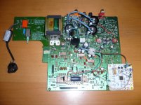
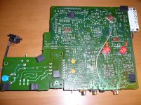
And by the way what is this little board pointed with the red arrow?I have search pictures on the web..and i don't see this add on later???board, on the CD-3.
Thanasis.
Looks like some kind of extra regulator circuit for the power supply. Are there any 78Lxx or 79Lxx regulators on it? Or maybe a few transistors with zeners.
I had installed a number of relay operated muting circuits onto quite a number of CD63s but unfortunately not on CD67. I am note sure where the control signal should connect but I am sure RAY will provide some information to you
Of course
Look here on my CD57 page, it has the same board as the CD67.
Regards,
Ray
Ray,thank you for the answers.There isn't any regulators on this board.Just transistors and zeners.Under is connected with the vertical board which is next to it.The regulators are all on the power supply board,2xlm317,2xlm337,1x7805,1x7806.Looks like some kind of extra regulator circuit for the power supply. Are there any 78Lxx or 79Lxx regulators on it? Or maybe a few transistors with zeners.
Thanasis.
Hi Ray
I've bought a 12v relay PCB as shown (similar to that used by Higlander) and I've looked at the suggestions on the mods page and your CD67 mods pdf regarding the relay. To be honest, I'm a all at sea with this aspect of the mod and wondered if you or other users could provide a bit of guidance. I've marked component swaps or where I think the wires should go but would you mind assisting me with the remaining terminals?
Is it a case of wiring to the correct terminal? I assume the onboard transistor switches the relay rather than recycling one of the muting transistors?
Picture and diagram of relay wiring
Help very much appreciated.
I assume that the base of QN7 or 8 is the 'input' signal. What about the ground contacts?
Looking at Ray's schematic for the CD53 - NO go to the emitters of QN7 and QN8 - would the collectors go the ground (with a resistor before connecting to GND)?
Ray - am I reading your schematic correctly?
Looking at Ray's schematic for the CD53 - NO go to the emitters of QN7 and QN8 - would the collectors go the ground (with a resistor before connecting to GND)?
Ray - am I reading your schematic correctly?
My 9th modding project
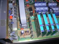
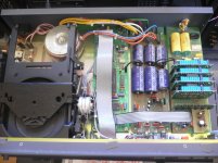
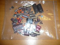
I am now working on my 9th CD63 modding project for my friend even though I have told everybody that I won't do that again !! Well friendship is friendship that I don't want to disappoint them.
I have completed about 85% of the mod and the CD63 at the moment performs very well as expected. What I need to complete is the relay operated muting circuit and change the stock transformer to 3 toroidal transformers. I am waiting for the components to arrive that will take some time especially the relay which is to be sent from Hong Kong.
I have uploaded a few pictures here for reference and you can also see the components I have changed which is shown inside the plastic bag.
I am now working on my 9th CD63 modding project for my friend even though I have told everybody that I won't do that again !! Well friendship is friendship that I don't want to disappoint them.
I have completed about 85% of the mod and the CD63 at the moment performs very well as expected.
What I need to complete is the relay operated muting circuit and change the stock transformer to 3 toroidal transformers. I am waiting for the components to arrive that will take some time especially the relay which is to be sent from Hong Kong. I have uploaded a few pictures here for reference and you can also see the components I have changed which is shown inside the plastic bag.
Attachments
- Home
- Source & Line
- Digital Source
- Marantz CD63 & CD67 mods list