Andy,
Already installed a XO clock (from Guido Tent) together with it's own powersupply. First a standard 7812 regulator with it's own small transformer (mounted behind the CDM12 on the underside of the bar running from left to right (in a KI model). Then the TL431 with the transistor from Tents schematic on a small PCB glue-ed on the side of the main PCB near the DAC (glue-gun, ideal!).
It is already feeding the clock power of the DAC (pin 28 if i recall correctly). This is done together with quite a few modifications described by Thorsten. Did this before i got the schematics and it still worked..") I have some pictures, i will post one or two here soon.
I have some pictures, i will post one or two here soon.
Again, thanx for the manual !!!
Guido
Already installed a XO clock (from Guido Tent) together with it's own powersupply. First a standard 7812 regulator with it's own small transformer (mounted behind the CDM12 on the underside of the bar running from left to right (in a KI model). Then the TL431 with the transistor from Tents schematic on a small PCB glue-ed on the side of the main PCB near the DAC (glue-gun, ideal!).
It is already feeding the clock power of the DAC (pin 28 if i recall correctly). This is done together with quite a few modifications described by Thorsten. Did this before i got the schematics and it still worked..
I have some pictures, i will post one or two here soon.Again, thanx for the manual !!!
Guido
Guido
Thanks for the info.
Try an LT1086 instead of the TL431, these things are really noisy (despite what you'll often read).
I know Thorsten et al think they are quiet, but they are wrong!
For best results I'd suggest running an LM317T off of the raw 10V supply that feeds the 5V reg, then add the LT1086 after this.
Andy.
Andy,
I know there is al lot of discussion about regulators. Maybe i'll try a different setup in the future. But it is inconvinient to take the player apart and put it back together again all the time. Do that often enough and it will give problems.
I also got my hands on two TDA1541A's, i am going to try a non-oversampling DAC with these. See how it works out. Since i have an old philips player (CD650, with the service manual this time , i can hook the DAC to the decoder without much problems. Easy then to get a first impression.
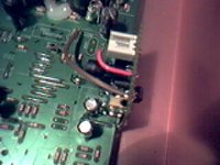
Anyway, here's the picture on the XO on the main PCB.
Guido
I know there is al lot of discussion about regulators. Maybe i'll try a different setup in the future. But it is inconvinient to take the player apart and put it back together again all the time. Do that often enough and it will give problems.
I also got my hands on two TDA1541A's, i am going to try a non-oversampling DAC with these. See how it works out. Since i have an old philips player (CD650, with the service manual this time
, i can hook the DAC to the decoder without much problems. Easy then to get a first impression.Anyway, here's the picture on the XO on the main PCB.
Guido
Attachments
Guido, you are very right saying "...to take the player apart and put it back together again all the time. Do that often enough and it will give problems." I have done it with my player tens of times over about two year period and now it's not working... I have been on and off repairing it for a month now but still can't figure out whats wrong with it..... : (
Anyway, these are great players with a lot of potential and well worth to modify.
The last mod I did was to leave only one side of the double opamp in circuit and after that run the signal to push-pull FET's at the output of HDAM. This gave the best imaging and depth of soundstage I've ever got from the player. Some time ago I tried to run the signal straight after the first opamp to amp, but it was not all that great. There were some positive changes regarding soundstage, but the player lacked the bass control and had kind of "running out of steam" sensation with some music. The HDAM buffer stage in circuit cured that and left only the positive : ) (remember to short the second side of opamp and HDAM input to ground if you do this mod..)
BTW. I have LM6172 opamps and no output el.caps. The last is I think the first and one of the most important things to get rid of.
Ergo
Hi ALW,
i succeded in downloading the file by upgrading to Netscape 6.2. Tried with a 56k modem first, worked ok, only the download would always stall after 10-30 min, even with the connection still being intact. Got a fried to download it from a DSL line...
Most interesting point about the manuals: entering the service mode, e.g. by pressing play and stop while turnin on player. Wonder if that works for Philips and Grundigs, too.
The much praised HDAM module does not look to special, particularly the input pair. Wonder what all that craze about the OSE and KI models was...
If I had one of those players, i'd probably want to get rid of the DAC first and then install some decent op-amps or discrete amps.
Eric
Get rid of the DAC!?!?!?
Eric,
The DAC in the CD63 is rather good, it's just poorly implemented in circuit.
It's design allows signififcant isolation of digital, analogue and oscillator sections, something very rare indeed.
Correct the faults and it's a marvellous CD player - you'd have to do an enormous amount of work to get an external DAC to perform to similar levels, owing to the problems of jitter through SPDIF.
The input pair is a matched device (2 transistors in 1 package), it's certainly better than most cheap op-amps. The main point though is you'd be wasting your time without correcting it's major deficiencies first.
IMHO the CD63, once most of it's major faults are corrected - almost all of which relate to PSU's and clock jitter, outperforms all the machines I've heard, up to the 1000 ukp mark.
Andy.
Could y'all provide specific guidance?
Ergo, Eric, Andy,
Could we propose a list of specific changes, in order of effectiveness? I'm an engineer and I cant even decipher the engineer-speak going on here, save one thing -
1. "The last is I think the first" - the decodes in my mind to the electrolytic caps being changed, apparently the output signal caps.
Something like "leave only one side of the double opamp in circuit" is like, well, which side did you pick? Any IC body numbers to reference? "run the signal to push-pull FET's at the output of HDAM" is something I can understand.
Andy, you make reference to "major faults" three times in your reply; could you please number them? I'd like to download the schematic and do some mods to my CD-63 and it would be great to plan it out and implement a step at a time.
If you want to keep the specifics secret, perhaps for business reasons, I understand.
On the other hand, it''d be great to see something like -
1. replace/eliminate output caps
2. rewire output FET circuit to source signal from U13, only
3. Disconnect DAC clock power and feed with independently shunt regulated +5V
4. Upgrade U13 to LM8272...
5. Disconnect +/-15V from U13, feed with independently shunt regulated +/- 12V
I really dont know - those are just guesses based in part on what I've read so far. Let's be specific.
Many ways to skin a cat
I don't like being specific on mods and effectiveness as many people look for different improvements, and one of the fun bits of being on this forum is trying different ideas and getting feedback from others.
But for my own viewpoint my sole criteria when assessing any 'improvment' is one of musical involvement and communication.
Things such as soundstage, imaging deep bass, sweet highs are all musical fluff if the music doesn't involve emotionally. I want to hear how good the musicians are, their interplay and abilities - it needs to make me dance, sing laugh etc. I want to know what and how a bass or guitar is being played, not just that there's an intrument that sounds 'nice'.
So if that is what you want, jitter is the fundamental thing to address, and every major fault in this player comes from PSU-derived problems IMHO. The 5V rail in particular is horrendously noisy and I feel certain the ultimate improvment would come from an external, multi-railed supply giving clean feeds which can then be regulated internally.
1. To start with the DAC oscillator gate needs a low noise PSU, dedicated to it only, and close to the DAC. Improve decoupling here too with a good low-ESR film or ceramic directly across the supply pins. This will bring rewards even if you elect to fit a better clock later, so do this one first.
2. Feed the 4 analogue DAC supplies from a single quiet PSU.
3. Change the JRC2114 op-amps for either LM6172's or AD825 modules.
4. Fit a low jitter clock (and make sure it has a quiet PSU feed!).
5. Change the DAC o/p filter caps for polystyrene 1% tol.
You'll get a player that is truly involving, punchy, musical and detailed, and that will outperform most I've heard up to a 1000ukp.
For details on how to do some of these mods (because implementation is critical - no point adding another reg if it's just as noisy as the original supply) take a look here: http://www.acoustica.org.uk/.
If you want music, jitter is fundamental, and it all comes from that noisy, heavy modualted 5V rail. If you look elsewhere on this forum you'll find spectral analyses of the 5 V rail, it's horrible!
A.
Joe, you are quite right. If I reread my posts with an eye of someone who hasn't spent countless hours inside this player it would be hard to keep up.... Well I at least try to make it better with the following...
First some links, likely you have already discovered them all
http://www.tnt-audio.com/clinica/cd67.html
http://www.tnt-audio.com/clinica/cd60pce.html
http://www.tnt-audio.com/clinica/cd63e.html
http://www.acoustica.org.uk/ -> clock hack
*****
IMO the tweak steps that should be made and order I suggest is good would be following
1) eliminate the output electrolytic caps from analog output (C656, C658, C655, C657)
I have replaced them with wire jumpers. It would be wise to check the DC component at output connector with multimeter. In my experience it's never more than abou +/- 20mV, which is mostly of no concern. Only if you have a true direct coupled amp where there are no caps in signal line it might happen that the DC component will also be amplified and sent to speakers. I think there is no commercial amp built this way, but some DIY projects might be.
2) Change the opamps. National LM6172 seems to be the most popular candidate and is the one I'm using.
Here the most important is to make sure you will place the additional decoupling caps to the supplies of opamp as close to pins as possible. I have 0.1uF polyprop caps from pins 4 and 8 to ground. When choosing the caps go for the ones that have as small dimensions as possible and as short legs as possible. Also place a cap on top of the opamp between +/- pins (pins 4 and 8). The value of this cap is not critical. Here you should pick some sort of SMD cap with as big capacitance as possible. I used some that were soldered off of some scrapped Intel PC motherboards. It is (at least I think so) non polar cap and the DMM measured it 20uF !!! I don't know if its right but it fits well on top of SMD opamps (I didn't get DIP cases from RS for some reason, even though the part nr. was right). A good place to look for ideas about opamps and decoupling is audioasylum forum.
3)Modify the clock. Install a sepparate one or use the description on acoutica.org site. I did my clock mod very sililar to that independently and as it turns out the techical solutions were similar and also our findings about changes in sound...
4)Better decoupling to supply lines. Use your imagination here.... One warning though, I once decided to change almost all the el. caps in the player for better ones (Nichicon xx, I don't remember the series at the moment). So, I replaced them and to some places I just put bigger values than stock. Well as it turned out I managed to overtweak a bit and now it takes about 30 sec before the display lights up I have studied it a bit, also with scope but can't fiqure out what causes the delay. Player starts normally and other than that there is no problem... so I have accepted it as just one more little thing that makes my player special.
****
I would suggest that it would be both wise and informative to make a few tweaks at the time. It is simpler to troubleshoot or reverse tweak and on the other hand it gives an idea of what kind of change any of these will make and do you like it or not.
It is also good if it would be possible to reverse any tweaks you'll do if needed. So when doing something try to think it over and if possible just cut the trace, leave one leg of a resistor open or wahtever...
****
Here is how I have my analog stage at the moment. Opamps are LM6172.
The blue lines are wire jumpers. The red crosses are places to cut a trace.....
First some links, likely you have already discovered them all
http://www.tnt-audio.com/clinica/cd67.html
http://www.tnt-audio.com/clinica/cd60pce.html
http://www.tnt-audio.com/clinica/cd63e.html
http://www.acoustica.org.uk/ -> clock hack
*****
IMO the tweak steps that should be made and order I suggest is good would be following
1) eliminate the output electrolytic caps from analog output (C656, C658, C655, C657)
I have replaced them with wire jumpers. It would be wise to check the DC component at output connector with multimeter. In my experience it's never more than abou +/- 20mV, which is mostly of no concern. Only if you have a true direct coupled amp where there are no caps in signal line it might happen that the DC component will also be amplified and sent to speakers. I think there is no commercial amp built this way, but some DIY projects might be.
2) Change the opamps. National LM6172 seems to be the most popular candidate and is the one I'm using.
Here the most important is to make sure you will place the additional decoupling caps to the supplies of opamp as close to pins as possible. I have 0.1uF polyprop caps from pins 4 and 8 to ground. When choosing the caps go for the ones that have as small dimensions as possible and as short legs as possible. Also place a cap on top of the opamp between +/- pins (pins 4 and 8). The value of this cap is not critical. Here you should pick some sort of SMD cap with as big capacitance as possible. I used some that were soldered off of some scrapped Intel PC motherboards. It is (at least I think so) non polar cap and the DMM measured it 20uF !!! I don't know if its right but it fits well on top of SMD opamps (I didn't get DIP cases from RS for some reason, even though the part nr. was right). A good place to look for ideas about opamps and decoupling is audioasylum forum.
3)Modify the clock. Install a sepparate one or use the description on acoutica.org site. I did my clock mod very sililar to that independently and as it turns out the techical solutions were similar and also our findings about changes in sound...
4)Better decoupling to supply lines. Use your imagination here.... One warning though, I once decided to change almost all the el. caps in the player for better ones (Nichicon xx, I don't remember the series at the moment). So, I replaced them and to some places I just put bigger values than stock. Well as it turned out I managed to overtweak a bit and now it takes about 30 sec before the display lights up
I have studied it a bit, also with scope but can't fiqure out what causes the delay. Player starts normally and other than that there is no problem... so I have accepted it as just one more little thing that makes my player special.****
I would suggest that it would be both wise and informative to make a few tweaks at the time. It is simpler to troubleshoot or reverse tweak and on the other hand it gives an idea of what kind of change any of these will make and do you like it or not.
It is also good if it would be possible to reverse any tweaks you'll do if needed. So when doing something try to think it over and if possible just cut the trace, leave one leg of a resistor open or wahtever...
****
Here is how I have my analog stage at the moment. Opamps are LM6172.
The blue lines are wire jumpers. The red crosses are places to cut a trace.....
Attachments
Got the manual!
Ahh, thanks guys - that's what I was hoping for. I think I have a much better idea of what to do, thanks to your posts!
A little story. I once had a Magnavox CD player that I pooged the heck out of. Bypassed every digital IC, replaced all the D/A filter caps with WIMA MKS, replaced the I/V and output op amps with an AD model, got rid of the MUTE transistors, got rid of the output coupling caps, ran a completely seperate, always energized power supply to the new output op-amps, bypassed them with WIMA MKPs, biased the op-amp outputs with a resistor to make them operate more class A, added a heat sink to the op-amp package and maybe some other a-specific stuff I dont recall...
I heard about the Marantz CD-63 and decided I wanted one. Did a side-by-side with the pooged phillips player and the Marantz at the dealer, using headphones. I could not hear any difference, so I passed on the Marantz.
A couple weeks later I bought the Marantz anyway, sold the Magnavox to a friend. GOSH I WISH I HAD THAT PARTICULAR UNIT BACK!
That being said, it's time to start all over again.

Anyone willing to email the PDF
for the service manual of Marantz CD63 etc.
Much appreciated,
Please send to rbroer@woodward.com
Rudolf
for the service manual of Marantz CD63 etc.
Much appreciated,
Please send to rbroer@woodward.com
Rudolf
DonJuan
I2S is pin 19 20 and 21 on the decoder (7345). But i am not shrue if Marantz is using the digital filter of the 7345. That would mean oversampling. Guess not, the DAC has its own. Check the datasheets and the freq of the I2S signals to figure it out.
Greetings,
Guido
I2S is pin 19 20 and 21 on the decoder (7345). But i am not shrue if Marantz is using the digital filter of the 7345. That would mean oversampling. Guess not, the DAC has its own. Check the datasheets and the freq of the I2S signals to figure it out.
Greetings,
Guido
Re: Get it whilst it's hot
Thank you for posting the CD63 service manual. My printer is now busy. I have a 63 and a 63KI so I will probably attack the cheapo one first. Since the board is quite fragile and I don't want to whip it in and out like a yo-yo, I will probably do all my mods in one go.
ALW said:
Thank you for posting the CD63 service manual. My printer is now busy. I have a 63 and a 63KI so I will probably attack the cheapo one first. Since the board is quite fragile and I don't want to whip it in and out like a yo-yo, I will probably do all my mods in one go.
Matching R's after the DAC
Hello EC8010!
While you're at it with the CD63, match the 10k and 27k resistors on the +/- inputs of the first opamp. I managed to do it within 0,1% tolerance. If you take all out + the ones in the headphone amp, you'll probably find a match.
It made as big a difference as taking the output caps out.
Check URL=http://db.audioasylum.com/cgi/m.pl?forum=tweaks&n=18343&highlight=CD63+hdam&session=]Dave Stanten's mods[/URL] for closer instructions.
Guess the matching damps out a lot of the noice coming from the DAc together with the signal.
I haven't even matched the 27k 0,1%, but the difference is stunning!
Cheers,
Tom
P.S. Changed the valve sockets and one 0,1uF cap on my Quad II, but I doubt that was the problem if there ever was one...
CD63 mods
Hello Zombie, thanks for the tips. I can order some 0.1% resistors and match them on a 4 1/2 digit DVM. However, it will be a while before I start playing with the CD players as I'm busy on another project at the moment.
If I were you, I would probably replace all three 100nF capacitors in the Quad II. A failure would just be too expensive. If you have access to a high-voltage insulation tester such as a Megger, you might like to test the old capacitors.
Zombie said:Putting a potentiometer in the place of the 27k to the ground you can obviously trim the circuit...
It's a long while since I looked at D/A design, so I'm a bit rusty. Is the idea of the dual differential (or push-pull) DAC to reduce distortion as the MSB changes? Thus, one would need to monitor distortion at perhaps -60dBFS whilst adjusting the 27k. Is that what you had in mind?
Those unbiased electrolytic coupling capacitors are certainly coming out! And I'm not too happy about the muting transistors either. A relay would be nicer. And as for the (probably ceramic) filtering capacitors on the first and second op-amps...
I haven't had a look yet to see how much fresh air there is inside to allow a clean supply for the clock and the DAC gate...
- Status
- This old topic is closed. If you want to reopen this topic, contact a moderator using the "Report Post" button.
- Home
- Source & Line
- Digital Source
- Marantz CD43 / 53 / 63 Service Manual