If you've got 680pf across 16 and 17 already then there's no lock to BCK - allegedly !!
250 pf will lock at 352.8 if memory serves me right.
Get the tightest tolerance you can - I fitted a 2% 250pf silver mica here and there was a noticeable gain - NOT massive but a gain nonetheless - you'll hear it. A bit cleaner is a safe explanation.
250 pf will lock at 352.8 if memory serves me right.
Get the tightest tolerance you can - I fitted a 2% 250pf silver mica here and there was a noticeable gain - NOT massive but a gain nonetheless - you'll hear it. A bit cleaner is a safe explanation.
I connected the reg as close as I could get to the +ve pin on 7220 (pin 24), follow the trace on the schematic and lift the chip side leg of the nearest component (a resistor in my case), this cuts off the 7220 from its existing supply. Replace the lifted leg with a feed from the reg. (By lifting one leg it's an easy job to back track if it doesn't work out)
The ground usually runs under the chip in the middle and, if you're lucky, may have a couple of solder blobs on there, I just connected my ground to that. Take care to leave the decoupling circuitry in there though.
The ground usually runs under the chip in the middle and, if you're lucky, may have a couple of solder blobs on there, I just connected my ground to that. Take care to leave the decoupling circuitry in there though.
If you've got 680pf across 16 and 17 already then there's no lock to BCK - allegedly !!
250 pf will lock at 352.8 if memory serves me right.
Get the tightest tolerance you can - I fitted a 2% 250pf silver mica here and there was a noticeable gain - NOT massive but a gain nonetheless - you'll hear it. A bit cleaner is a safe explanation.
I cant remember the value I used and I cant see it easily but its a close tolerance polystyrene cap that was picked off EC's list of caps that should produce a lock
") I've not tried Mica here, only film and styrene.
I've not tried Mica here, only film and styrene.I connected the reg as close as I could get to the +ve pin on 7220 (pin 24), follow the trace on the schematic and lift the chip side leg of the nearest component (a resistor in my case), this cuts off the 7220 from its existing supply. Replace the lifted leg with a feed from the reg. (By lifting one leg it's an easy job to back track if it doesn't work out)
The ground usually runs under the chip in the middle and, if you're lucky, may have a couple of solder blobs on there, I just connected my ground to that. Take care to leave the decoupling circuitry in there though.
Good advise. When you start to introduce separate regs for individual devices, you want the connection as close as possible to the pin that you're supplying. You also want the decoupling cap as close as possible. I think I've seen a quote here on the forum recently that every mm counts! In reality, its often easier and tidier to use vacant holes in the pcb. For example, often a supply will have a film cap very near the pin you are supplying and an elco fairly nearby. I tend to remove the film cap and put the elco where that was. That will leave the holes where the elco were to mount a reg! In the CD50, they use smt caps under the board instead of through hole film caps. This means you can only fit the elco's where they were originally. However, there is normally a feed resistor which can be removed. This will isolated the original supply and give you somewhere to feed the output of your new reg. This is how I fitted the reg to the 7220 last night. If you look at the picture that Mayday posted the other day, you will see a resistor just above the philips symbol. If you remove this, you can use the left hole to supply 5v to 7220 pin 28. In this case, its within a couple of mm of the pin so its pretty ideal.
When are you going to fit those film caps mayday? Let us know what you think. Remember it often takes a good few days of constant playing for things to settle down after installing new components. I always leave my players running to itself for at least 48hrs after each mod to see if I'm happy with the changes. Having said that, I have the house to myself this evening so I'm actually doing some listening at the moment.....I'm sure the urge to turn on the iron will get me at some point tho!
I cant remember the value I used and I cant see it easily but its a close tolerance polystyrene cap that was picked off EC's list of caps that should produce a lock
Good advise. When you start to introduce separate regs for individual devices, you want the connection as close as possible to the pin that you're supplying. You also want the decoupling cap as close as possible. I think I've seen a quote here on the forum recently that every mm counts! In reality, its often easier and tidier to use vacant holes in the pcb. For example, often a supply will have a film cap very near the pin you are supplying and an elco fairly nearby. I tend to remove the film cap and put the elco where that was. That will leave the holes where the elco were to mount a reg! In the CD50, they use smt caps under the board instead of through hole film caps. This means you can only fit the elco's where they were originally. However, there is normally a feed resistor which can be removed. This will isolated the original supply and give you somewhere to feed the output of your new reg. This is how I fitted the reg to the 7220 last night. If you look at the picture that Mayday posted the other day, you will see a resistor just above the philips symbol. If you remove this, you can use the left hole to supply 5v to 7220 pin 28. In this case, its within a couple of mm of the pin so its pretty ideal.
When are you going to fit those film caps mayday? Let us know what you think. Remember it often takes a good few days of constant playing for things to settle down after installing new components. I always leave my players running to itself for at least 48hrs after each mod to see if I'm happy with the changes. Having said that, I have the house to myself this evening so I'm actually doing some listening at the moment.....I'm sure the urge to turn on the iron will get me at some point tho!
I'll try to make time to fit the filmcaps tomorrow and possibly replace/parallell some caps in the PSU.
On a swedish forum I post on, one member worried about rectifier diods taking a hit with the 22000uf TSUP installed..should I swap diodes? To what?
Enjoy your listening time now
Cool, Post you findings here.
I've never had a problem but its a valid point so I thought I'd check the diode specs.
The diodes are IN4002. These are rated at 1A constant and 45A peak non repetitive surge current. In addition, I doubt the transformer is capable of delivering more than a few amps peak. I doubt you could do any damage with the initial surge current to charge the cap at switch on. Once the cap is charged, you'll not be drawing much additional current at all.
Irons been on! Hooked in some film caps in place of the Nichicon MUSE BP's - nice! Another quick win. I'd forgotten how much I hate elco's in the signal path even if they are half decent caps!!! They are only Wima std film caps too! Imagine what some Mundorf supreme would do!!!!!! lol
Cool, Post you findings here.
I've never had a problem but its a valid point so I thought I'd check the diode specs.
The diodes are IN4002. These are rated at 1A constant and 45A peak non repetitive surge current. In addition, I doubt the transformer is capable of delivering more than a few amps peak. I doubt you could do any damage with the initial surge current to charge the cap at switch on. Once the cap is charged, you'll not be drawing much additional current at all.
Irons been on! Hooked in some film caps in place of the Nichicon MUSE BP's - nice! Another quick win. I'd forgotten how much I hate elco's in the signal path even if they are half decent caps!!! They are only Wima std film caps too! Imagine what some Mundorf supreme would do!!!!!! lol
Isn't it great!
Small things making a big difference
Irons been on! Hooked in some film caps in place of the Nichicon MUSE BP's - nice! Another quick win. I'd forgotten how much I hate elco's in the signal path even if they are half decent caps!!! They are only Wima std film caps too! Imagine what some Mundorf supreme would do!!!!!! lol
I knew you would - this has got you going again
Thanks for the PM's btw - I'm now ' on it ' too
Andrew
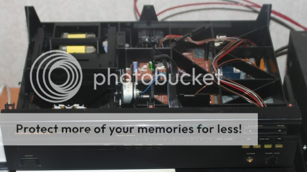
One quick win! If you are not going to use the variable audio out (the board on its own on the right) unplug it!!!! This will remove it from the +/- 15v rails. These are the rails that run the opamps in the output stage and the -15v is also for the TDA.
Do I just unplug all connectors and “jank” it out?
The Caps before the regs are a little more tricky!! The general rule of thumb with these "Smoothing" caps is bigger is better!! I've tried various options from tagging additional 1000uF caps to the bottom of the PCB through to big Panasonic TSUP 10,000uF and 22,000uF on short wires with the caps glued to the back plate!! The caps I'm talking about are 2703, 2713, 2707 and 2711. You can try Panasonic FC which you may be able to up the uF and still fit into the space. If I was keeping the player, I'd go for the TSUP option with leads! If you want to, you can change the PSU diodes to schottky type. Something like 11DQ09 can be had for about 30p each. I wouldn't say diodes makes a significant difference on their own but they do add up in the big picture.
If I can’t get more TSUP’s, what other low ESR caps would you recommend? Preferably ones that are easily found on for example ebay? This would be 3x10000uF/16-25V right with as short as possible leads to the pcb ringt?
OR, solder smaller values that’ll fit on the pcb. Any recommendations for this option?
I would replace the caps after the regs (2704,2714,2708 & 2712) with 470uF Rubycon ZLH
If I can’t find ZLH’s for a reasonable price(have to rely on ebay since I can’t get them from Swedish stores without a company) what would you recommend as replacement that are easily available?
You could also link the output caps direct to the output sockets bypassing the muting circuits. If you do this, you'll also need to isolate the output socket centre pins from the PCB. Possibly a good time to replace the output sockets with something slightly more exotic??
How do I go about bypassing the mute circuit? If I swap output sockets, were do I connect them to GND and how do I connect digital out?
Long list of questions, and I’m sure there’ll be more
REmoved the bottom cover:
PSU:
TDA1541/SAA7220:
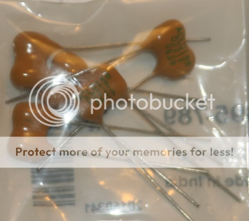
Found some 220pF Caps.
Silver-Mica:
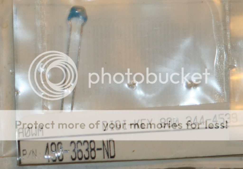
Ceramic:
Also found a Regulated PSU I had forgotten about. It's AC-DC, but could easily be converted to DC-DC. Rectifiers are BYV27-150. This old LM317 regulator of any good to me in this projekt?:
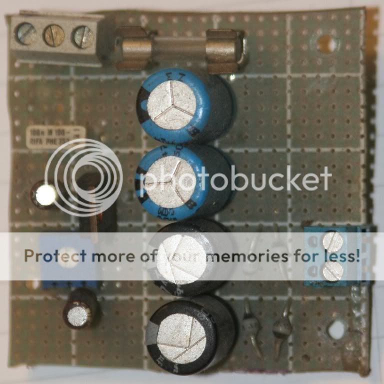
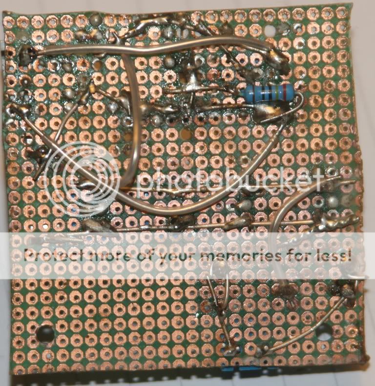
As I said, it's old...wasn't that good at soldering back then....
PSU:
TDA1541/SAA7220:
Found some 220pF Caps.
Silver-Mica:
Ceramic:
Also found a Regulated PSU I had forgotten about. It's AC-DC, but could easily be converted to DC-DC. Rectifiers are BYV27-150. This old LM317 regulator of any good to me in this projekt?:
As I said, it's old...wasn't that good at soldering back then....
If you've got 680pf across 16 and 17 already then there's no lock to BCK - allegedly !!
250 pf will lock at 352.8 if memory serves me right.
Get the tightest tolerance you can - I fitted a 2% 250pf silver mica here and there was a noticeable gain - NOT massive but a gain nonetheless - you'll hear it. A bit cleaner is a safe explanation.
What about 220pF? Any good or useless for this?
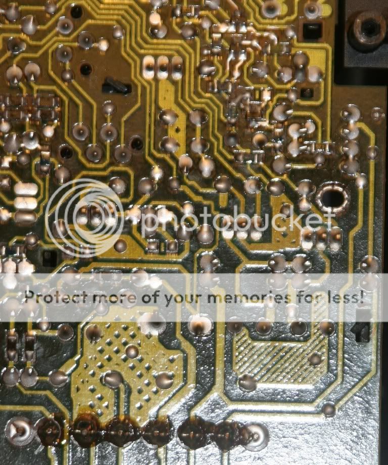
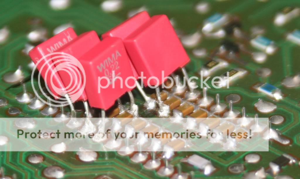
Wima's in place(ended up soldering them in parallell to the SMD's), haven't listened yet though..
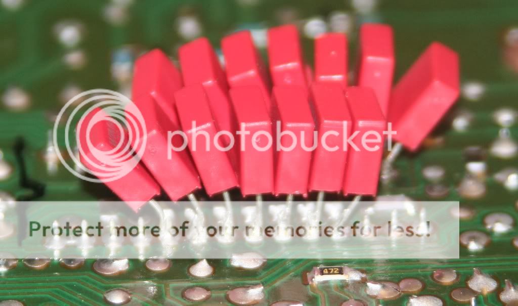
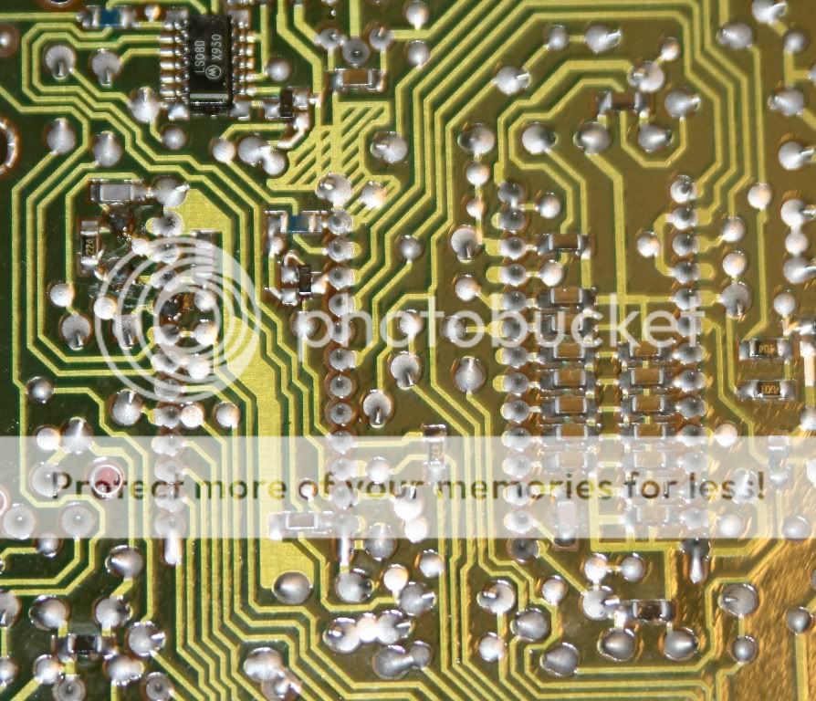
Get buzz from my multimeter between (bottom row from the left) Wima1 and the closest point and Wima4 and the closest point. Which appears to be ok if you look at the pic after this one.
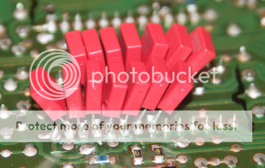
Get buzz from my multimeter between (bottom row from the left) Wima1 and the closest point and Wima4 and the closest point. Which appears to be ok if you look at the pic after this one.
Impressions from the first hour of listening, cd, amp etc was cold when the hour started.
My notes:
A bit less "muddy", more space, more separation.
Nothing huge, but definetly audible! Even the GF said she could here the difference
Vocals and instrument sound more "natural, true"
Improved soundstage.
Enjoyed D.A.D - laugh n' a half more than before the mod(I like that song).
Music listened to: D.A.D - Good clean family entertainment you can trust, No doubt - Tragic kongdome
In conclusion from only the first hour of listening.
I can't wait to hear what the other mods will improve
It's really nice and intresting to make one mod at a time, listen to what that mod did, and then go on to the next one...addictive
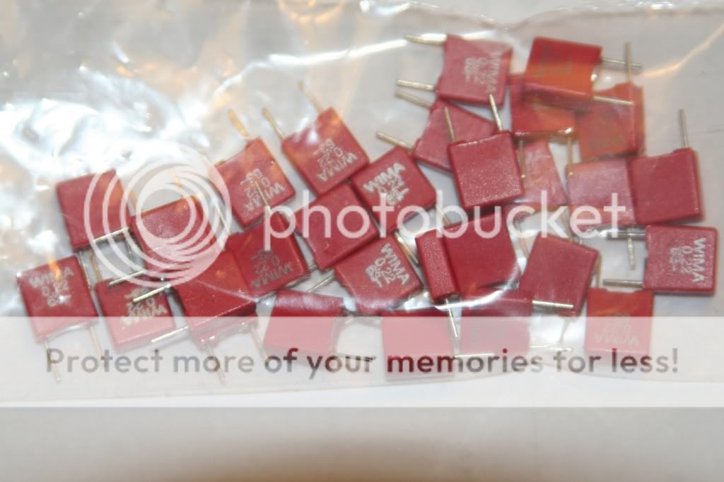
Just a small warning: WIMA is produced in Germany (meaning there are many fakes of Chinese origin around)...The bits that arrived today
Just a small warning: WIMA is produced in Germany (meaning there are many fakes of Chinese origin around)...
Yes, no doubt...seems to be fakes of everything floating around.
These were bought from Poland
- Status
- This old topic is closed. If you want to reopen this topic, contact a moderator using the "Report Post" button.
- Home
- Source & Line
- Digital Source
- Marantz CD-50 and CD-60, TDA1541, CDM4/19