Ok Please look at my pic and see if I'm doing this right. 1) Signal comes in here. 2/3) the various resistors. 4a) Goes out to ground 4b) Goes around the switch to the out.
All well with this picture? Thanks for the help. First picture is how I'm going to lay it out
All well with this picture? Thanks for the help. First picture is how I'm going to lay it out
Attachments
Hi athos:
From an electrical point of view, your resistor arrangement looks correct if I'm reading your picture correctly. But, from a designer point of view, it's not an optimal design because you have all the resistors all the time connected to the output with one lead. Those resistors can pickup surrounding noise, like small antennas. The standard approach might be better.
Regards,
Milan
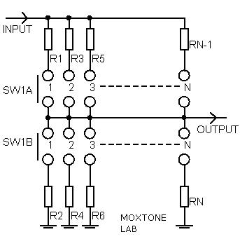
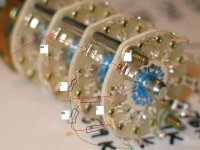
Ok moamps
Is this how I would do it then?
The signal (in) is connected to the copper ring on deck 3, goes through the resitor and either out to the chip amp or to the ground deck 4, through the resitor there and out to the copper ring on deck 4 which is the ground wire.
Another picture, green is copper ring, black lines are the resistors, I'm trying to make it clear.
Thanks for all the help
Attachments

- Status
- This old topic is closed. If you want to reopen this topic, contact a moderator using the "Report Post" button.
- Home
- Amplifiers
- Chip Amps
- Making a step attenuator for a Chipamp