Heath,
After several tried the surface mount device from an old pc motherboard that I feel gain some confident and ready to move to the next stage.
My intention to use your board are mainly to experience B+ power supply on my linestage. The current B+ at 250v to 10M45s as a CCS, idle draw about 40mA. What will be the value for R7, R8, R2 and R4? The R2 and R4 to set the Vout, is there a fixed 1.25v between LM317's output and adjust?
Sidney
Sydney,
Correct, the LM317 does what it needs to to keep 1.25 between output and adjust pins.
Here's what you need to know to design this thing:
1. Input voltage
2. Output voltage
3. Min current
4. Max current
If everything is CCS loaded Min and Max current would be the same. When you say that current B+ is 250V, you want to regulate that down a bit, then?
Here's the issue with the CRC filter: the 'R' will drop voltage. That voltage drop is dependent on how much current is being drawn from the supply, which means we still don't know what input voltage to design for.
You can do one of two things: figure out what the output of that CRC filter is when it is loaded or eliminate the RC and just have the rectifier feed a single capacitor. I use just rectifier to capacitor and haven't been able to measure ripple on the output (I just own an old Tektronix 465 for testing this).
Let me know what you decide to do.
An o'scope generally isn't sensitive enough to measure the output ripple of a Maida regulator. I use a regular AC voltmeter for this. It'll measure ripple + noise, but for my purposes that is adequate.
The purpose of the CRC filter is to reduce the ripple on the supply. The Maida regulator serves the same purpose. There's no harm in removing the last RC and just letting the regulator do the job.
~Tom
The purpose of the CRC filter is to reduce the ripple on the supply. The Maida regulator serves the same purpose. There's no harm in removing the last RC and just letting the regulator do the job.
~Tom
")
So we have about 380V in and 250V out.
R7 will have 115V(380-250-15V) across it. If you shoot for 5mA that gives you 23kOhms. The nearest 5% value is good enough. It will dissipate .6W so I would get a 2 to 3 W resistor.
For R8 I shoot for 1.5V drop at normal current. 1.5/.040 = 37.5 Ohms. Pick the nearest value. It does not have to be precise. This resistor is a "current limiter" but I wouldn't count on it saving the pass devices if you accidently short the output. If you accept the fact that the regulator will nearly certainly die if you short the output, you could also just use a jumper here instead of the resistor.
As far as R2 and R4 go, I would go with Mouser p/n 588-TA310PA50K0JE for R4. This is a 30K 10W resistor and will fit.
You will then have 248.75V across a 30K resistor, so 8.29mA. So now we know that R2 will have 1.25V across it and 8.29mA through it so it must be a 150.78 Ohm resistor. Find the nearest 1% 0805 surface mount resistor to this value and you will be set.
Let me know if you have any more questions.
An o'scope generally isn't sensitive enough to measure the output ripple of a Maida regulator. I use a regular AC voltmeter for this. It'll measure ripple + noise, but for my purposes that is adequate.
I got a cheaper meter and it just gets confused when I connect it to HVDC on the AC setting. I should have spent the money for a Fluke.
I should have spent the money for a Fluke.
Bingo! I have never regretted blowing $400 on a calibrated HP 34401A multimeter on eBay. I have two of them....
~Tom
Hey Heath,
I got your card very promptly and they look great. You vendor does a nice job for the price. Pardon my manners for not commenting sooner. Things get hectic around here.
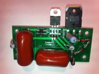
I built one up last night out of parts I had around, and I will test it when I find a suitable pot (I'm keeping this first one adjustable). BTW, most of these parts came off a power supply board from a Flat screen TV. I recommend them highly when they can be had for free. Lots of big caps, heatsinks and cleaver means of isolating and clamping devices to the heat sinks. I used a Toshiba K2611 N Channel Mosfet rated for 900V.
A few questions I have:
1. Can you explain the purpose of D2 and D4. I can't imagine what these opposed diodes can do since no dc current can pass in either direction. I see that in the Maida, he uses a 1K resistor tied to the middle of the Darlington.
2. I don't have any surface mount components and I forgot about them on the last Mouser order. I'd like to work around that at least until I get another order out. I think we all agree that D1 is optional?
3. R1, the gate stopper, is not on the Maida notes but those are NPN bipolars not FETs. Can I get away by soldering wire across those pads until I get the surface mount resistor?
4. There is an implication by omission in the Maida discussion as well as MJs 3rd ed. drawing of this circuit, that the LM317 doesn't need a heat sink. Have you noticed if it runs hot? I suppose that with a 12 volt zenier (my choice) it will run hotter than that the Maida with the 6.2 volt D9
Thanks
I got your card very promptly and they look great. You vendor does a nice job for the price. Pardon my manners for not commenting sooner. Things get hectic around here.
I built one up last night out of parts I had around, and I will test it when I find a suitable pot (I'm keeping this first one adjustable). BTW, most of these parts came off a power supply board from a Flat screen TV. I recommend them highly when they can be had for free. Lots of big caps, heatsinks and cleaver means of isolating and clamping devices to the heat sinks. I used a Toshiba K2611 N Channel Mosfet rated for 900V.
A few questions I have:
1. Can you explain the purpose of D2 and D4. I can't imagine what these opposed diodes can do since no dc current can pass in either direction. I see that in the Maida, he uses a 1K resistor tied to the middle of the Darlington.
2. I don't have any surface mount components and I forgot about them on the last Mouser order. I'd like to work around that at least until I get another order out. I think we all agree that D1 is optional?
3. R1, the gate stopper, is not on the Maida notes but those are NPN bipolars not FETs. Can I get away by soldering wire across those pads until I get the surface mount resistor?
4. There is an implication by omission in the Maida discussion as well as MJs 3rd ed. drawing of this circuit, that the LM317 doesn't need a heat sink. Have you noticed if it runs hot? I suppose that with a 12 volt zenier (my choice) it will run hotter than that the Maida with the 6.2 volt D9
Thanks
Attachments
D2 and D4 are back to back Zeners, to clamp the gate voltage. Around 15V should do.
The "zener diode clipper" circuit is new to me. I just read up on it. Any voltage over the zener value gets clipped. I'll have to look at that on the scope later.
So is the purpose of R1, the gate stopper, to limit the current through the zeners?
Humm, I substituted the spec'd Mosfet for a 900v one I had on hand. I hadn't really given that much thought until now. Is that okay or does it require different diodes values?
Toshiba K2611 DATASHEET
Toshiba K2611 DATASHEET
The "zener diode clipper" circuit is new to me. I just read up on it. Any voltage over the zener value gets clipped. I'll have to look at that on the scope later.
So is the purpose of R1, the gate stopper, to limit the current through the zeners?
The purpose of the zener clamp is to limit Vgs on the MOSFET to a safe value. Most MOS don't tolerate more than +/-20 V across the gate oxide. Some MOS devices (like the STW12NK95Z I like to use) have the zeners built in.
The purpose of the gate stopper is (usually) to prevent parasitic oscillations in the gate drive circuit.
~Tom
According to the data sheet you linked, the 2SK2611 has internal protection diodes on the gate.
Would you be so kind as to point out where on the datasheet that is mentioned. I just don't see it. Or don't know what to look for.
- Status
- This old topic is closed. If you want to reopen this topic, contact a moderator using the "Report Post" button.
- Home
- Amplifiers
- Tubes / Valves
- Maida Regulator PCB