I tried one disc magnet on the chassis and several discs at the underside of the platter
How do you attach the discs to the underside of the platter and how do you achieve sufficient precision?
Can you please provide us with photographs?
Marco
Something like this http://www.vinylengine.com/phpBB2/a...php?pic_id=6163
Please elaborate a bit on how you did get it centred with sufficient precision.
And what magnet is on the other side. A ring magnet? How did you get that one centred precisely?
MArco
Hello Marco,
I was not sure who you were asking about construction methods so I did not want to interupt before (I hope you don't mind now).
I designed and built the particular magnetic bearing that sq225917 has built a version of, and describes. We know each other well and I hope he agrees with this.
The bearing I use has one large ring element and another element consisting of a circular, ring, array of cylinder magnets. I built a number of prototypes before arriving at my final realisation (five prototypes).
I used a CNC Router to produce the supporting structure as geometric accuracy is extremely important for this type of design, Initally I used acrylic but my final design is from HIPS.
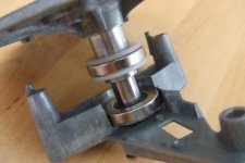
Below are a few pictures of the first prototype that I built. Sorry, but I do not have any pics of the final design. In the photographs the bearing consists of two circular arrays of cylinder magnets but (as said before) the final design replaced the lower array with a single ring magnet. In addition, the increased magnetic field of the later ring magnet allowed me to use much fewer cylinder magnets for the top most array. The construction methods are largely similar between prototypes though.
I was not sure who you were asking about construction methods so I did not want to interupt before (I hope you don't mind now).
I designed and built the particular magnetic bearing that sq225917 has built a version of, and describes. We know each other well and I hope he agrees with this.
The bearing I use has one large ring element and another element consisting of a circular, ring, array of cylinder magnets. I built a number of prototypes before arriving at my final realisation (five prototypes).
I used a CNC Router to produce the supporting structure as geometric accuracy is extremely important for this type of design, Initally I used acrylic but my final design is from HIPS.
Below are a few pictures of the first prototype that I built. Sorry, but I do not have any pics of the final design. In the photographs the bearing consists of two circular arrays of cylinder magnets but (as said before) the final design replaced the lower array with a single ring magnet. In addition, the increased magnetic field of the later ring magnet allowed me to use much fewer cylinder magnets for the top most array. The construction methods are largely similar between prototypes though.
An externally hosted image should be here but it was not working when we last tested it.
An externally hosted image should be here but it was not working when we last tested it.
An externally hosted image should be here but it was not working when we last tested it.
Ynwoan,
Thank you. Now I understand.
From the picture in http://www.vinylengine.com/phpBB2/a...php?pic_id=6163 I got the impression that you managed to find a method which didn't involve CNC routing. Unfortunately that is not the case ...
I'm afraid I have to be clever al by myself.
Marco
Thank you. Now I understand.
From the picture in http://www.vinylengine.com/phpBB2/a...php?pic_id=6163 I got the impression that you managed to find a method which didn't involve CNC routing. Unfortunately that is not the case ...
I'm afraid I have to be clever al by myself.
Marco
Hi Marco,
I'm glad if I helped a little. I'm afraid I'm not sure which pic you are referring to as the link you have provided does not go to any specific picture (this may be because I have deleted many of my old posts from vinylengine).
In actual fact the ring magnet I use essentially has a CNC machined spacer to locate it concentrically with regard to the main bearing and this could be made by hand (carefully). In addition, it is possible to recreate much of my work without access to CNC equipment (it's just more difficult). Accuracy is important though - bear that in mind and have fun.
Clearaudio does it with two simple magnets. I also think it is possible with two strong ringmagnets. See post #115 + 122. This is simple to make (without CNC work??). Problem with my attempt was a worn out and to short sliding bearing. I used a Garrard which I modified now to a fully satisfying inverted ceramic-steel bearing. So the magnetic bearing is no longer needed. But it was an interesting project tough.
Attachments
I also think it is possible with two strong ringmagnets
I've tried with 2 loudspeaker compensation magnets. These happened to be way to weak, so i want to replace one of them with a super magnet. As to my knowledge super ring magnets aren't sold, I have to make a ring with smaller ring magnets.
MArco
(in this thread you can see the turntable I'm working on: http://www.diyaudio.com/forums/showthread.php?s=&threadid=109696
ring size
http://www.neotexx.com/ have neo rings up to 50mm or 2"
Anders
deduikertjes said:
As to my knowledge super ring magnets aren't sold, I have to make a ring with smaller ring magnets.
[/URL]
http://www.neotexx.com/ have neo rings up to 50mm or 2"
Anders
I tried neodymium ring magnets with outer diameter 50 mm, inner diameter 30 mm, height 5 mm from a local supplier:
www.euromagnet.hu
Here are some data of the N35 material that I used:
http://www.euromagnet.hu/Neodimium s tbl.htm
But two opposite ring magnets like this proved to be way too strong for elevating the 3 kg mass of the Thorens TD160S platter. The bottom magnet self-sticked to the steel subplatter. I will follow YNWOANs method and mount some small disc magnets on a steel plate attached to the bottom of the inner platter. I suppose the secret is to have the opposing magnets as close to each other as possible, in order to reduce stray field that may disturb the pickup. Hopefully the steel magnet holder disc will serve also as a magnetic shield, and I can play with the number of the small magnets.
You will find that the stray magnetic field is quite localised and, if kept within the diameter of the record label, should not interfere with the cartridge. In addition, the steel disk will definitely help to deflect stray magnetic field.
The specific level of compression that the magnetic field is under makes quite a big difference to the success of a magnetic bearing. The field wants to be relatively 'stiff' when compressed. The only way to have any control over this issue is (as far as I can see) to use a method similar to my own - I ring magnet and a second array of individual cylinder magnets set into a ring shape. By increasing, or decreasing, the number of individual cylinder magnets used one is able to customise the strength of the magnetic field and match it to the mass of the platter.
The specific level of compression that the magnetic field is under makes quite a big difference to the success of a magnetic bearing. The field wants to be relatively 'stiff' when compressed. The only way to have any control over this issue is (as far as I can see) to use a method similar to my own - I ring magnet and a second array of individual cylinder magnets set into a ring shape. By increasing, or decreasing, the number of individual cylinder magnets used one is able to customise the strength of the magnetic field and match it to the mass of the platter.
Ynwoan has a point with the possibility to regulate the compression. If you use two ringmagnets instead of one ringmagnet and several smaller cylinder magnets, to adjust the compression, you have experiment with:
1 The size and force type of ringmagnets. In my experience with most magnets there is some information about the ‘maximum weight the magnet can lift’. Take 2/3 of this weight and this is your maximum platter weight. This is what you have to experience yourself!
2 Adjust the weight of the platter by putting more weight on. I did this with sheets of flexible self sticking lead/rubber anti-vibration plates.
I used two tiny Neodymium ringmagnets R25mm x 15mm x 0,5mm With a maximum weight lift for one magnet 4,95kg. The platter of my Garrard weights about 2,3 kg. With this platter there was a gap of 2mm between the magnets (could easily be changed between 1,5-3mm depending on the weight of the platter). With my experience the compression is not that critical to get a descend floating bearing.
Above is only my short experience with my unsuccessful attempt. But I really think it is possible to make a nice TT bearing with just two cheap ringmagnets. There is just almost nothing to find about this subject magnetic TT bearings for DIY. So boys and girls experiment and share us your success or in my case failure.
My turning magnetic bearing in action.
Triumph, there seems to be a lot of friction in your main bearing (from that video any way).
Just for clarification, my reference to adjusting the strength of the magnetic field was not so that it could be floated appropriately, it was so that the compliancy of the circuit could be adjusted. This is important as the bearing (if fully floated) effectively becomes a filter - the frequency at which it operates is set by how compliant the magnetic field is.
Just for clarification, my reference to adjusting the strength of the magnetic field was not so that it could be floated appropriately, it was so that the compliancy of the circuit could be adjusted. This is important as the bearing (if fully floated) effectively becomes a filter - the frequency at which it operates is set by how compliant the magnetic field is.
Not only there is friction in my video but also wobbling. This is caused by the gliding bearing and the minimum weight of the subplatter.
A magnetic bearing is not without resistance! The construction than is shown has actually more resistance than my present inverted bearing. The difference is a magnetic bearing is more silent. There is less mechanical noise, depending of the quality and construction of the sliding bearing. For me that is less important, I use an idler drive that has no real black background.
Ynwoan never thought that with a magnetic bearing it is possible to adjust its frequency. That’s some useful information. It can be used like a suspended sub-chassis. Only how to adjust the frequency and which frequency, how to measure? Good idea though!
Hmm...properly applied, there should be less friction than in a conventional bearing - not zero, but less. Certainly, this is what I found. Clearly the bearing liners still create a significant level of friction but the point contact is relieved.
Triumph, I think the reason that your friction levels are higher is because the magnets are not truly perpendicular to the shafts they are mounted to and the two opposing surfaces of the magnets are not absolutely parallel. As a result, when the platter turns the uneven application of magnetic repulsion causes uneven lateral forces to be applied to the main bearing shaft (effectively trying to twist it diagonally in the bearing journal) and this causes the bearing shaft to be pressed with increased pressure against the inner bore of the bearing - so increasing friction. However, thinking about it, it is quite possible that I am misinterpreting the specific construction of your bearing.
Triumph, I think the reason that your friction levels are higher is because the magnets are not truly perpendicular to the shafts they are mounted to and the two opposing surfaces of the magnets are not absolutely parallel. As a result, when the platter turns the uneven application of magnetic repulsion causes uneven lateral forces to be applied to the main bearing shaft (effectively trying to twist it diagonally in the bearing journal) and this causes the bearing shaft to be pressed with increased pressure against the inner bore of the bearing - so increasing friction. However, thinking about it, it is quite possible that I am misinterpreting the specific construction of your bearing.
The frequency can be calculated from the platter mass and magnet "spring" compliance. The compliance can be measured from the displacement caused by the platter mass. Ultimately, the frequency will be inversely proportional with the displacement, and it can be easily measured. No dynamic measurement is necessary, a simple static additional mass method is sufficient (delta x divided by delta m). The only question is: what is the optimum frequency?Triumph said:Only how to adjust the frequency and which frequency, how to measure?
Hi ynwoan, not posted on here for ages. Im the guy who brought his modded lenco round.
Still using the lenco but am finishing a slate plinth for it and have remade the arm a couple of times now.
Im still very intreaged about your bearing ideas and am still considering trying something similar myself.
It was ages ago that i spoke to you though and im sure ive asked you this before but...
My concern is that my TT is idler drive and the idler wheel presses up onto the underneath of the platter. Do you think this would be a problem?
Im just wondering, as the magnets are trying to push the platter up, is the platter effectively lighter? If you try and raise the platter does it feel as heavy as usual or does it lift reasonably easy untill the magnet gap increases then the weight of the platter comes back?
Does that even make sense") ?
?
Still using the lenco but am finishing a slate plinth for it and have remade the arm a couple of times now.
Im still very intreaged about your bearing ideas and am still considering trying something similar myself.
It was ages ago that i spoke to you though and im sure ive asked you this before but...
My concern is that my TT is idler drive and the idler wheel presses up onto the underneath of the platter. Do you think this would be a problem?
Im just wondering, as the magnets are trying to push the platter up, is the platter effectively lighter? If you try and raise the platter does it feel as heavy as usual or does it lift reasonably easy untill the magnet gap increases then the weight of the platter comes back?
Does that even make sense
?Hiya - and yes, it does make sense.
I guess the platter is effectively bearing (no intended pun) down with less force - how much of an issue that is rather depends on the weight of your platter and how much force the idler wheel applies to the underside of the platter (I would have thought).
I guess the platter is effectively bearing (no intended pun) down with less force - how much of an issue that is rather depends on the weight of your platter and how much force the idler wheel applies to the underside of the platter (I would have thought).
- Status
- This old topic is closed. If you want to reopen this topic, contact a moderator using the "Report Post" button.
- Home
- Source & Line
- Analogue Source
- Magnetic turntable bearing