The new can is stuffed already
I don't fully understand your post. The can is new correct?
Multisection caps have symbols stamped on the can next to the ratings and then on the mica near the tabs. Usually the are square, triangle, D etc. These are positive leads. The can itself is negative. You only tie two together if you need a capacitance equal to the sum of two sections. Always be careful to observe the voltage ratings. It's common for the cans to contain sections with differing voltage ratings. You wouldn't want to tie a 50 volt section to a 450 and then use it on the B+.
(1) quad can cap - 50uf x4 @ 350 volts. Use 1 section
for C1A, 2 for C1B, 1 for C1C.
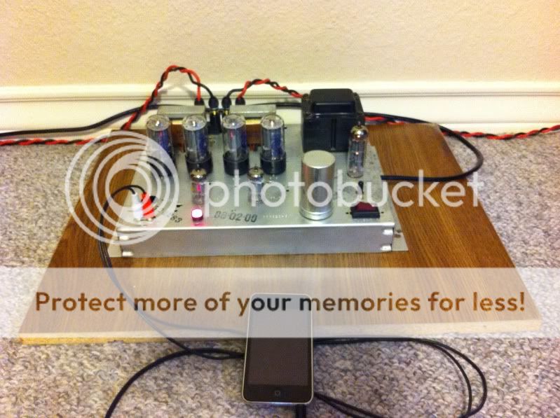
This is the can I recieved....I guess I'm just asking if it's "remove & replace" as is.....
Sorry if this is a stupid question, but everything else is completed, cap replacement, resistors out of tolerance, switch, fuse, RCA speaker stand-offs, power LED. I just want to complete this amp correctly. I appreciate everyone's help thus far, this amp is coming together very nicely - & will be appreciated for years I'm sure. Thanks for clarification
for C1A, 2 for C1B, 1 for C1C.
This is the can I recieved....I guess I'm just asking if it's "remove & replace" as is.....
Sorry if this is a stupid question, but everything else is completed, cap replacement, resistors out of tolerance, switch, fuse, RCA speaker stand-offs, power LED. I just want to complete this amp correctly. I appreciate everyone's help thus far, this amp is coming together very nicely - & will be appreciated for years I'm sure. Thanks for clarification
Sorry i didnt have time yesterday for a photo.. however i have the following:
3x40uf 400v suntan with all negative leads joined together and then going to the chassis ground. The other 3 pins from each goes inbetween the resistors that were on the bottom of the can cap.
The 4th one i have is an elna 40uf 25V (bypassed with 0.1uf wima MKP) which is bypassing the 180ohm resistor for the bias on the 4 output tubes i think.
I've got a 30uf bypassing the 180 Ohm now, which the way I understand it - this is for the audio bias. This amp is completed now except for the auto high gloss paint ( or similar ) up top, and the wood trim around the chasis. I will post final pictures upon completion, and want to thank all the people here whose knowledge and help made this amp a reality for me. Thank you

Last edited:
Also these values were changed from 0.047 + 0.0047, to 0.1 + 0.01 (which gave a much needed bass boost).
Did you leave the voltages stock? Are these the orange drops people talk about. I would like a little more bass from the amp if possible
Did you leave the voltages stock? Are these the orange drops people talk about. I would like a little more bass from the amp if possible
You can add some capacitance to the couplers yes - but it may well be the design goal was to limit the LF extension. The output trafos may not be real happy handling large bass signals. So don't go overboard!
Once you get that new can cap installed you might find the bass is improved significantly even without changing the coupling cap values.
Last edited:
Leave the cap can and go for 4 individual caps under the chassis. Its generally known that using 4 caps in a can like that can interfere with each other.
Interfere with each other?? I have no idea what you mean, can you explain?
There's no need to do the discrete caps thing... The brand new can cap he's got will do an excellent job, it's FAR easier to install, and it works well with his power supply.
The 100 Ohm resistor between the 1st cap section and the EZ81 makes 50 uf as a 1st section a good choice. He then uses (2) 50 uf sections paralleled to improve the screen supply, and uses a 50 uf 4th section to replace the stock voltage amp/PI decoupling cap.
He is using a better quality discrete 47 uf cap as the cathode bypass cap, taking that cap out of the can is a good idea.
Yes, i heard that the cathode bypass cap is the problem with being in the can and causing hum on the output because of this. Also increasing the coupling caps to 0.01uf and 0.1uf extended the bass response for me alot, so thats worth doing.
The capcans i know of do get very hot too, which is why i opted to have 4 individual caps under the chassis to minimize this.
The original speakers in the console would have needed smaller coupling caps to limit the LF as you suggest...
I have not changed any other values so the voltages are close to the original spec.
The capcans i know of do get very hot too, which is why i opted to have 4 individual caps under the chassis to minimize this.
If a can capacitor is getting warm, it should be replaced at once before further use. If DC leakage across one of the sections is great enough to create heat, it certainly presents an unwelcome load to the power supply which is very likely to cause it's failure.
You can and should anticipate this sort of problem, and thereby reduce the likelihood of such a failure, by selecting a slo-blow fuse that is sized very close to operating current as measured with a DMM.
The cap cans i know of do get very hot too, which is why i opted to have 4 individual caps under the chassis to minimize this.
(Full disclosure - I sent him the parts we're discussing)
His new can is 85 C rated and has a 350 volt rating (400 surge) on all sections. It won't get hot - the heat almost always is from leakage of an old stock cap. A fresh, properly rated can cap - especially with an indirectly heated tube rectifier and 100 Ohm resistor in series between the trafo and the cap - is simply loafing.
There's no need for discrete caps in this case - a newly made part exists that does the job very nicely. And it's MUCH easier to install for someone without a lot of experience with this sort of thing.
A hot cap can can also indicate oscillations... which is why i separated them all.
But there will be other symptoms as well - I've never seen a hot can that was the ONLY symptom of oscillation.
Indeed, i thought best not to have the can anyways...make the job easier if anything did happen to one of them.
Anyhow, im happy with how mine performs with the changes i made (even though ive never heard of suntan brand??). Not even with my ears in the speaker cones can i hear any hiss or hum.
Also drives them to decent levels *Mordaunt short mezzo 6, 89db*... sounds much better than my old Dared VP-20 6L6 monoblock setup.
Last edited:
Perhaps you should build a simple passive preamp. I have one around here that is nothing more or less than a volume pot installed in a small box with cables coming out each end. I picked up a good set of vintage cables with small diameter knurled brass RCA fittings and spring stress relief that fit the vintage RCA spacing that is often a problem on the Maggies, and then cut them in half. It looks like an interconnect with volume pot in the middle.
Mouser has an ALPS 100K dual audio taper HERE that would be quite good. Bourns can set you up for a couple of bucks with either 100K or 50K pots HERE.
Of course you could also install said pot in the amp chassis.
Mouser has an ALPS 100K dual audio taper HERE that would be quite good. Bourns can set you up for a couple of bucks with either 100K or 50K pots HERE.
Of course you could also install said pot in the amp chassis.
Perhaps you should build a simple passive preamp.
Right on! However, keep the 1:10 impedance rule in mind. The O/P impedance of a driving entity should be at least 10X smaller than the I/P impedance of the driven entity, for maximum wave form fidelity. Build the passive control center (preamp combined with passive = oxymoron) out of either 2X 10 KOhm log. taper parts or a single, ganged, stereo control. All commercial CDPs are quite capable of driving 10 KOhm controls well (IHF "standard"
") ). Use short, low capacitance, cables that are hard wired ("captive") to the control(s). That holds the number of purely mechanical connections in the signal path down.
). Use short, low capacitance, cables that are hard wired ("captive") to the control(s). That holds the number of purely mechanical connections in the signal path down.$2.73 buys Mouser stock # 313-2420F-10K, which is an Alpha Taiwan stereo/ganged carbon control that sounds pretty good. Better quality, both physically and in sonics, is a PEC (Canada) milspec hot molded carbon control sourced from DigiKey. Of course, the PEC stuff costs several X as much as Alpha Taiwan.
Last edited:
- Status
- This old topic is closed. If you want to reopen this topic, contact a moderator using the "Report Post" button.
- Home
- Amplifiers
- Tubes / Valves
- Magnavox 8608-10