It looks as though one of the xfrmers is shorted. The owner stated "He may have run to low of a load"!
I can power it up without it blowing a 40 amp fuse, but soon after my power supply shuts down(overload). It is a 25amp inductive supply.
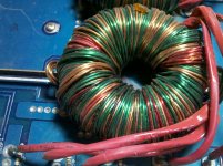
Attached are some pics of the xfrmer and pcb where it was warm.
Due I bother trying to find a replacement xfrmer or just return it as not fixable?
I can power it up without it blowing a 40 amp fuse, but soon after my power supply shuts down(overload). It is a 25amp inductive supply.
Attached are some pics of the xfrmer and pcb where it was warm.
Due I bother trying to find a replacement xfrmer or just return it as not fixable?
Attachments
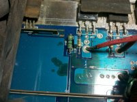
It looks like something corrosive marked the board. Electrolyte from a capacitor is the most likely suspect but if it was near a battery, that could have caused it also.
Have you tried pulling the FETs out of this supply to see if the amp would power up and produce clean audio?
Is this an individual winding that's burned (driver supply or similar) or is it part of a larger winding in the primary or secondary?
If it's a driver supply winding, you can easily replace it if it's all on the top layer.
If it's part of a larger bundle, you could cut the burned section of that individual strand free from the rest of the bundle and replace it with another strand.
I can scrape the masking away and the copper is clean, I don't think it is corrosion.
Have you tried pulling the FETs out of this supply to see if the amp would power up and produce clean audio?
I haven't tried pulling fets, yet.
This amp has two supplies and it looks to only have affected the one transformer. Those windings are melted every where on it. Most of the damage is on the secondary side though.
Is the primary windings under the secondary?
I don't know how the windings are laid down.
It appears that there is only one burned wire. It wraps around several times but it looks like you could unwrap it relatively easily.
Look at the terminals for the various components in the area. They look a bit fuzzy like they're corroded also.
It appears that there is only one burned wire. It wraps around several times but it looks like you could unwrap it relatively easily.
Look at the terminals for the various components in the area. They look a bit fuzzy like they're corroded also.
I have been looking at the xfrmer windings and it does look easy enough to unwind and repair. I use the term easy very loosely! I have only done this once and that was on a 250a2.
Look at the terminals for the various components in the area. They look a bit fuzzy like they're corroded also.
The terminals are covered in thermal paste and dirt. This amp was covered in old dust.
The power supply and output fets all measure ok in circuit, which surprises me. The xfrmer is the weak part of this design, I guess?
If I get the xfrmer back in order would this amp warrant new fets all the way around? He wants to use it in a competition. I would think the fets were stressed enough to warrant a change to new parts.
The winding likely shorted to one of the terminal windings where it exits from under the core. This is a bad point for many transformers.
You'll have to make the call on the FETs. I don't know how badly they were stressed. If the backs of them don't show signs of overheating (taking the imprint of the insulator) and don't have any little solder beads where the metal and plastic meet, they may be OK.
You'll have to make the call on the FETs. I don't know how badly they were stressed. If the backs of them don't show signs of overheating (taking the imprint of the insulator) and don't have any little solder beads where the metal and plastic meet, they may be OK.
Thanks again. got them.
I removed the transformer and the secondary windings are trashed. They are missing the coating on the wires and a few are melted in half. If I counted correctly I had 16 full windings and the primary looks to have 4.
The primary is missing a little coating, I can separate those and isolate with kapton tape. Time to order some wire, any thoughts on where?
ebay
https://www.amidoncorp.com/
Copper Magnet / Enameled & Bare Wires
You'll need a dial caliper to get the exact diameter to determine the gauge. The re-wound one needs to match the other one pretty closely, especially if it's going to be run at its lowest rated impedance.
Solder strippable wire (what's used originally) is easier to strip (heat with a hot soldering iron). The high-temp stuff has to be stripped by scrapping the coating.
I've only seen a few amps that use one supply for the positive rail and a second supply for the negative rail. The Alpine MRV-1507 is the only one that I can think of right now but there are a few others. Generally, each power supply drives two rectifiers (one positive and one negative). The output of the rectifiers for each supply are connected in parallel.
The secondary is likely a normal center-tapped winding.
Of course, I've never worked on a 5082 so your amp may be different.
The secondary is likely a normal center-tapped winding.
Of course, I've never worked on a 5082 so your amp may be different.
This has my curiosity, I will check tonight and verify.
One more question, why such a huge fuse on the input? (300A) Wouldn't it make sense to lower this size to protect the amp? Fusing next to the battery will save the vehicle from fire I suppose and shut the amp down, but some won't fuse at the battery.
One more question, why such a huge fuse on the input? (300A) Wouldn't it make sense to lower this size to protect the amp? Fusing next to the battery will save the vehicle from fire I suppose and shut the amp down, but some won't fuse at the battery.
- Status
- This old topic is closed. If you want to reopen this topic, contact a moderator using the "Report Post" button.
- Home
- General Interest
- Car Audio
- MA audio MA5082HX