Thanks Jacco and Chris
I will probably use On Semi parts. In the past, it was really easy for me to do matched sets with On Semi outputs because they measured aboutthe same in a batch.
A last question:
Toshiba specify for the 2SC3281 a Cob of 270 pF TYP.
On Semi specify for MJL3281 a Cob of 600 pF MAX.
One specify this spec as TYP and the other as MAX. Do these different specifications can change something or they perhaps means the same thing ?
Thanks a lot
Marc
Collector capacitance is important for Vas and drivers, think drivers of high input capacitance Mosfets.
Not the main theme for BJT EF output stages.
High SOA corresponds with a big die, a big die means a high Cob number. Cob of NPN and PNP devices are usually widespread, only on some Mosfet output stages capacitance is balanced by placing a matching capacitor in parallel with the low "C" Mosfet device.
Cob of the 2SA1302 is 470pF Typical
Mail me if you'd like the more difficult to find 2SA datasheet, to big to post here.
problem still not resolved
Today, I replaced the output transistors on the faulty channel. I used on semi MJL1302 and MJL3281
After turning on the amplifier, I let it warm, adjusted the dc offset and tried to adjust the bias at 110mv across the emitter resistor of output transistors. The maximun dc voltage across the .22ohm emitter resistors i can get is 40mv.
At least, I have the same dc voltage across the six .22 ohm emitter resistors.
Another problem I saw is that the dc offset voltage is unstable. it fluctuates continually between 9 and 15 mv. Each time i try to lower it to 0 mv, it returns automatically near 10mv. The pot now can't go lower.
Any idea of this strange problem? I'm going crazy with this amp
Thanks
Marc
Hi Marc,
Sit back and take a deep breath. You have low bias drive and DC offset instability.
Two faults, possibly two different problems. Can you monitor the output of the op amp and also the output terminals? I want to see if the op amp output is wandering around by itself, or trying to correct a DC fault. Also make sure the op amp supplies are stable.
We will attack low bias later. It won't hurt anything for now. To be safe, reduce the bias current to 10 ~ 15 mV in case the problem corrects itself. Could be a bit of solder flash or another intermittent problem. Normally I would attack the bias fault first.
-Chris
Hi Marc,
All right. There is something seriously wrong in the front end. This may also explain your low bias. The DC offset integrater is doing it's best to correct things.
At this point you may be further ahead to simply remove and test all you signal transistors. While you are there, measure the gains and match the ones that work in pairs.
Your 10 mV may be the natural offset of this op amp. Try to replace it as well.
-Chris
I found a cold solder so here is what I get now on the servo op amp .
The bias seems stable with no bias on the outputs (I work on the board without heatsink on outputs)
I tried to raise the bias and got 40 mv like it was.
Pins
1- 1.742
2- -.003
3- -.008
4- -14.4
5- 0
6- -.003
7- -5.8
8- 14.4
Marc
The bias seems stable with no bias on the outputs (I work on the board without heatsink on outputs)
I tried to raise the bias and got 40 mv like it was.
Pins
1- 1.742
2- -.003
3- -.008
4- -14.4
5- 0
6- -.003
7- -5.8
8- 14.4
Marc
I begin to hate this amplifier
Dc offset is ok since in changed the output transistors
I checked all the bias transistors and found that Q225 was short. I changed it and tried to bias the amplifier without heatsink. When the output transistors began to heat, the bias raised rapidly so I thought that I had won the game.
I replaced the heatsink on output transistors and everything is still too low. 40 mv is the max bias setting I can get. I should have 100mv across the .22 ohm emitter resistors.
I plugged a toaster as a 16 ohm load to the speaker terminals and drove the amplifier just near clipping at 2khz. The bias can reach 80mv at full throttle before clipping.
If I bypass the heat sensing transistors at A-203, the bias will fall to 0 on idle. I also replaced the relay Ry202.
The amplifier has symetrical clipping and the power is ok
I'm really tired to take the board and heatsinks outside the amp each time I have to work on it.
Any idea about what can I do now ?
Thanks
Marc
Today, I still worked on the beast.
I took the limiter transistors Q222, Q223, Q224, Q225 out of the board to see if limiters were the problem. Without them, the problem is the same.
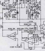
I made some measurements on A203 where the transistors connected as diodes are placed on the heatsink. Here are the values I got.
A203 0mv bias 40 mv bias 100 mv bias
pin bad channel bad channel on good channel
1 1.5v 1.7 1.2v
2 0.85v 1v 0.6v
3 0.47v 0.2v 0.7v
4 1.1V 0.89v 1.3v
Can these number helps to diagnose something ? ?
I checked every diodes and transistors and they are good
Thanks
Marc
I took the limiter transistors Q222, Q223, Q224, Q225 out of the board to see if limiters were the problem. Without them, the problem is the same.
I made some measurements on A203 where the transistors connected as diodes are placed on the heatsink. Here are the values I got.
A203 0mv bias 40 mv bias 100 mv bias
pin bad channel bad channel on good channel
1 1.5v 1.7 1.2v
2 0.85v 1v 0.6v
3 0.47v 0.2v 0.7v
4 1.1V 0.89v 1.3v
Can these number helps to diagnose something ? ?
I checked every diodes and transistors and they are good
Thanks
Marc
Oups
Some deformatting
A203 pins
1
2
3
4
0mv bias on bad channel related to pins
1.5v
0.85v
0.47v
1.1V
40 mv bias on bad channel related to pins
1.7
0.85v
0.47v
1.1V
100 mv bias on good channel related to pins
1.2v
0.6v
0.7v
1.3v
Hi
Did you ever repaired Luxman M-05?
Mvh
M-05 (x2)
Im not sure if I have a problem with the idling current. When following the service manual instructions of setting the current at 100 mV after being switched on for 1 minute then retest at 110mV after 5 minutes of being on I find after 20 minutes of use the amp changes to 146mV. Is this normal?
The heat sinks are not touchable due to the heat. They seem way to hot, to be correct. If I turn the current to 50mV, the unit is no where as hot. Is this a issue? The fans work well, one is slightly noisy. My unit runs on 240V mains power, and the unit is rated 230V. Not sure if the difference of 10V creates the extra heat.
I don't want to cook the amp.
Ok - reviving an old thread. I just got a m05 and one powet board is not working.
But, looking at the output board schematic it sure looks like a standard push pull configuration with both npn and pnp transistors. How can Luxman claim it to be pure class A? What am I missing?
But, looking at the output board schematic it sure looks like a standard push pull configuration with both npn and pnp transistors. How can Luxman claim it to be pure class A? What am I missing?
But, looking at the output board schematic it sure looks like a standard push pull configuration with both npn and pnp transistors. How can Luxman claim it to be pure class A?
Perhaps you should brush up on your class A definition
")
I did. I can't find anyplace or circuit in any textbook, web page, etc. that uses complimentary-symmetry outputs in a true class A configuration. It looks to me like Luxman is just biasing hard the outputs so that the A-B configuration conducts hard all the time. I have a decent background - having taught electronics at the college level for years and spent my summers working as an audio repair technician for years. What am I missing?? maybe, the definition of class A has changed?? ...Class A Amplifier. The most commonly used type of power amplifier configuration is the Class A Amplifier. The Class A amplifier is the simplest form of power amplifier that uses a SINGLE type (or bank) switching transistor in the standard common emitter circuit configuration.
- Status
- This old topic is closed. If you want to reopen this topic, contact a moderator using the "Report Post" button.
- Home
- Amplifiers
- Solid State
- Luxman M-05 105W/channel class A