No, I haven't tried that method of compensation.
I'm afraid I don't recognize it, do you know what it is called?
Oh and JCX, I forgot to answer your question for the reader, I'll guess that the baker clamp would greatly improve positive clipping by preventing saturation of Q8.
What better time to go over the top than when using low voltage, low power devices that cost 10¢ each (explosions are less financaly painful
") ). I also find amplifier distortion somewhat more noticable in headphones than through loudspeakers. Thank you for taking a look at my design.
). I also find amplifier distortion somewhat more noticable in headphones than through loudspeakers. Thank you for taking a look at my design.
I'm afraid I don't recognize it, do you know what it is called?
Oh and JCX, I forgot to answer your question for the reader, I'll guess that the baker clamp would greatly improve positive clipping by preventing saturation of Q8.
But this is not so much the case with a 32R output buffered headphone amp and a trifle over the top.
What better time to go over the top than when using low voltage, low power devices that cost 10¢ each (explosions are less financaly painful
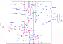
). I also find amplifier distortion somewhat more noticable in headphones than through loudspeakers. Thank you for taking a look at my design.my view of this is that it can be viewed as two amps in one: the first consists of the LTP (Q1+Q2)+ associated VAS (Q3+Q4). This is very much an opamp.
the 2nd is a JLH-styled follower, consisting of an input stage with current feedback (Q7), its VAS (Q8) and an EF buffer / current amplifier (Q9+Q10).
If it is really for a headphone application, either one (with minor modification) is sufficient.
the 2nd is a JLH-styled follower, consisting of an input stage with current feedback (Q7), its VAS (Q8) and an EF buffer / current amplifier (Q9+Q10).
If it is really for a headphone application, either one (with minor modification) is sufficient.
high feedback designs sometimes have poor overload recovery; with the 2 pole compesation I used there were massive bursts of oscillation in clipping - the baker clamp is just the first layer of taming bad clipping behavior, at last count I was diode clipping 3 nodes, added a current limit transistor and series Z in the vas to limit output V sat currents to survivable levels
V gain in the output stage is very useful in distortion reduction, following Cherry's argument distortion from a stage is reduced by the gain between it and the input - the classic feedback aproximation. but it turns out that the reduction in signal level due to gain beween a distorting stage and the output is the more powerful distortion reduction mechanism (for 3rd order and higher nonlinearities) so maximizing V as well as I gain in the output stage is very profitable
V gain in the output stage is very useful in distortion reduction, following Cherry's argument distortion from a stage is reduced by the gain between it and the input - the classic feedback aproximation. but it turns out that the reduction in signal level due to gain beween a distorting stage and the output is the more powerful distortion reduction mechanism (for 3rd order and higher nonlinearities) so maximizing V as well as I gain in the output stage is very profitable
thanh,
your values for the 2-pole compensation are not the best for the vas, with a high impedance output drive you want to minmize the load on the output where the load shunts current to ground and is "throwing away" gain - I think you will find that equal value C is more efficient in this sense - just double the required high frequency stabilizng Cdom value to get the new value for the 2 series caps
if you can extend the compensation loop to include a output buffer stage then the higher C load on the output you show is good because it minimizes the C seen at the compensation network input
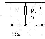
This is my amp !Amp can only work with C12=200p ,C13=1n . If its values is smaller , amp will not work . Although amp can work , there still has thumb sound when I turn off power => amp still ocssilate .
If C12 is smaller than 100p , ltp+cfp will defeat Blameless ,distortion is about 200uV-300uV at 25V output voltage
If a compensate cap is use for CFB stage , amp will also ocssilate . It is hard to know why a compensate cap cause ocssilation .
A cap from collector of Q8 to -input will also cause ocssilate .Perhaps only Leach can use this compensate method
Using a resistor at emitter of Q9 will produce a noise quite much . It is to easy to hear although volume is set al low level . Perhaps this resistor decrease gain of Q9 and cause RF exist in amp .
Current amp still has sound from Radio stations if volume is set at high level .
Attachments
- Status
- This old topic is closed. If you want to reopen this topic, contact a moderator using the "Report Post" button.
- Home
- Amplifiers
- Headphone Systems
- LTP+CFB Headphone Amp (spiced)