There's not much published info on the web about these.
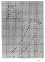
This link will take you to a post-office data sheet giving you limited informatoin
CV1660 @ The Valve Museum
If you were looking for the triode curves, you'd probably have to buy a few, if you don't have some already, and trace them or have someone trace them for you. Maybe another member has done so already, I'm not sure.
I've been meaning to get some for a little while and do have a curve tracer but the purchase price in the UK is a little steep so I've not taken the plunge.
Interesting DHT valve though.
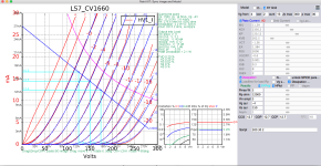
**** LS7_VT82_CV1660 ******************************************
* Created on 05/05/2024 13:11 using paint_kit.jar 3.1
* www.dmitrynizh.com/tubeparams_image.htm
* Plate Curves image file: /Users/zoran/Desktop/Model_Paint_Tools/Graph/
* Data source link:
*----------------------------------------------------------------------------------
.SUBCKT LS7_VT82_CV1660 1 2 3 ; Plate Grid Cathode
+ PARAMS: CCG=12.7P CGP=12.7P CCP=12.7P RGI=2000
+ MU=11.29 KG1=2356.2 KP=120.12 KVB=202.5 VCT=-1.56 EX=1.384
* Vp_MAX=300 Ip_MAX=30 Vg_step=2 Vg_start=4 Vg_count=13
* Rp=12000 Vg_ac=3 P_max=3 Vg_qui=-4 Vp_qui=150
* X_MIN=108 Y_MIN=45 X_SIZE=646 Y_SIZE=630 FSZ_X=1536 FSZ_Y=798 XYGrid=true
* showLoadLine=y showIp=y isDHT=n isPP=n isAsymPP=n showDissipLimit=y
* showIg1=n gridLevel2=n isInputSnapped=n
* XYProjections=y harmonicPlot=y dissipPlot=y
*----------------------------------------------------------------------------------
E1 7 0 VALUE={V(1,3)/KP*LOG(1+EXP(KP*(1/MU+(VCT+V(2,3))/SQRT(KVB+V(1,3)*V(1,3)))))}
RE1 7 0 1G ; TO AVOID FLOATING NODES
G1 1 3 VALUE={(PWR(V(7),EX)+PWRS(V(7),EX))/KG1}
RCP 1 3 1G ; TO AVOID FLOATING NODES
C1 2 3 {CCG} ; CATHODE-GRID
C2 2 1 {CGP} ; GRID=PLATE
C3 1 3 {CCP} ; CATHODE-PLATE
D3 5 3 DX ; POSITIVE GRID CURRENT
R1 2 5 {RGI} ; POSITIVE GRID CURRENT
.MODEL DX D(IS=1N RS=1 CJO=10PF TT=1N)
.ENDS LS7_VT82_CV1660
*$
Attachments
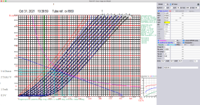
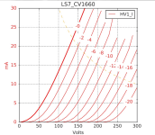
Spic model for other measurement.
main difference in Vct value.
I am wondering how the measurements are taken in the huge Ia region that exceeds max values?
Up to 64mA
.
cheers
main difference in Vct value.
I am wondering how the measurements are taken in the huge Ia region that exceeds max values?
Up to 64mA
.
cheers
Code:
**** LS7_VT82_CV1660_01 ******************************************
* Created on 05/05/2024 14:03 using paint_kit.jar 3.1
* www.dmitrynizh.com/tubeparams_image.htm
* Plate Curves image file: /Users/zoran/Desktop/Model_Paint_Tools/Graph/
* Data source link:
*----------------------------------------------------------------------------------
.SUBCKT LS7_VT82_CV1660_01 1 2 3 ; Plate Grid Cathode
+ PARAMS: CCG=12.7P  CGP=12.7P CCP=12.7P RGI=2000
+ MU=11.29 KG1=2356.2 KP=94.89 KVB=91.12 VCT=0 EX=1.384
* Vp_MAX=420 Ip_MAX=64 Vg_step=1 Vg_start=2 Vg_count=12
* Rp=12000 Vg_ac=3 P_max=3 Vg_qui=-4 Vp_qui=150
* X_MIN=171 Y_MIN=120 X_SIZE=1118 Y_SIZE=747 FSZ_X=1841 FSZ_Y=973 XYGrid=true
* showLoadLine=y showIp=y isDHT=n isPP=n isAsymPP=n showDissipLimit=y
* showIg1=n gridLevel2=n isInputSnapped=n
* XYProjections=y harmonicPlot=y dissipPlot=y
*----------------------------------------------------------------------------------
E1 7 0 VALUE={V(1,3)/KP*LOG(1+EXP(KP*(1/MU+(VCT+V(2,3))/SQRT(KVB+V(1,3)*V(1,3)))))}
RE1 7 0 1G  ; TO AVOID FLOATING NODES
G1 1 3 VALUE={(PWR(V(7),EX)+PWRS(V(7),EX))/KG1}
RCP 1 3 1G   ; TO AVOID FLOATING NODES
C1 2 3 {CCG} ; CATHODE-GRID
C2 2 1 {CGP} ; GRID=PLATE
C3 1 3 {CCP} ; CATHODE-PLATE
D3 5 3 DX ; POSITIVE GRID CURRENT
R1 2 5 {RGI} ; POSITIVE GRID CURRENT
.MODEL DX D(IS=1N RS=1 CJO=10PF TT=1N)
.ENDS LS7_VT82_CV1660_01
*$
Attachments
- Home
- Amplifiers
- Tubes / Valves
- LS7/CV1660