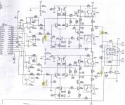
I have succesfully direct coupled the output by shorting the output cap and installing a dc offset nulling trimmer (indicated by the yellow highlighted components)
I now wish to short out the two resistors R119 and R219 47ohms to lower the output impedence to see how it affects the drive into a quite low input impedence of my next stage which is around 6kohms to see if it sounds any better, can everyone comment before I try it, will it be stable still? will it osscillate? it should drive better? I don't have much experience with darligtons BDX33's and BDX34's
Cheers George
Attachments
georgehifi said:I have succesfully direct coupled the output by shorting the output cap and installing a dc offset nulling trimmer (indicated by the yellow highlighted components)
I now wish to short out the two resistors R119 and R219 47ohms to lower the output impedence to see how it affects the drive into a quite low input impedence of my next stage which is around 6kohms to see if it sounds any better, can everyone comment before I try it, will it be stable still? will it osscillate? it should drive better? I don't have much experience with darligtons BDX33's and BDX34's
Cheers George
If the output transistors are adequately heatsinked, you might want to consider increasing the bias.
Re: Re: Lowering the output impedence of this dac's output
Heatsinks that can be done, what do you suggest to change to up the bias, I'm always in favour of more Class A , I have zero expirence in Darlingtons.
Just did the shorting of the R119 and R219 and had a quick listen, I had the inkling that the bottom end seamed stronger and more defined, not huge difference, but worth the trouble.
Cheesr George
rfbrw said:
If the output transistors are adequately heatsinked, you might want to consider increasing the bias.
Heatsinks that can be done, what do you suggest to change to up the bias, I'm always in favour of more Class A , I have zero expirence in Darlingtons.
Just did the shorting of the R119 and R219 and had a quick listen, I had the inkling that the bottom end seamed stronger and more defined, not huge difference, but worth the trouble.
Cheesr George
Measure the voltage across emitter resistors R114/5 and R214/5. Dividing that by the value of those resistors, 10 ohms, will give you the current bias current, so to speak. Using that as a starting point you can then increase the bias by lowering value of the emitter resistors.
That's a simple way rfbrw. But as it is, with the 10ohm emiter resistors in, it should be quite stable, if I lower the emiter resistor are'nt we delving into making the output less stable and maybe prone to occilate if it sees some weird high interconect capacitance ?
Cheers George
Cheers George
georgehifi said:That's a simple way rfbrw. But as it is, with the 10ohm emiter resistors in, it should be quite stable, if I lower the emiter resistor are'nt we delving into making the output less stable and maybe prone to occilate if it sees some weird high interconect capacitance ?
Cheers George
The emitter resistors are there for thermal stability and are often a lot smaller but you could always pose the question in the solid state forum for another view.
R119, R219 would isolate the output amp from capacitive load. You might experiment with smaller value, but shorting them doesn't seems to be a wise idea.
If you need very low output resistor, the coil//resistor approach looks like a hit.
http://www.jensen-transformers.com/datashts/oli3.pdf
If you need very low output resistor, the coil//resistor approach looks like a hit.
http://www.jensen-transformers.com/datashts/oli3.pdf
banana said:R119, R219 would isolate the output amp from capacitive load. You might experiment with smaller value, but shorting them doesn't seems to be a wise idea.
If you need very low output resistor, the coil//resistor approach looks like a hit.
http://www.jensen-transformers.com/datashts/oli3.pdf
Very nice, first time I've seen these, I will definatly get some.
Thanks George
I could offer suggestions I believe will improve measurable performance if a higher technical quality dac I/V-buffer is what you are seeking
but by the evidence of that discrete transistor "op amp" with 4 MHz ft darlingtons in weak Clas AB bias I guess the designer was more interested in introducing some "sound effect" - I wouldn't want want to unknowingly mess with someone's fuzz box cricuit
assuming you want to technically improve the circuit my 1st mod would be to lose the discrete op amp, but you might want to start with Class A biasing all 4 of the I/V op amp outputs with ~ 5 mA from the negative rail - very specific to NE5532/4 where the pull down is very much slower than the internal NPN pull up half of the output stage - I don't recomend this generally but it really is applicable to the NE5532 in a I/V stage
deep Class A biasing the discrete op amp's output would help but I can't imagine tweaking this to within an order of magnitude of the gain accuracy and distortion performance of even another NE5532/4 per the datasheet circuit, at 6K load you have only 500uApp so it isn't even clear Class A bias of a replacement NE5532/4 would matter - I bet the datasheet circuit wins any measureable performance comparison for your load
your Vos tweak tirm pot may be upsetting the diff to single end conversion - ideally R103/RR105 = R104/R108 and any Vos should be added elsewhere - the fact that you need Vos adj is further evidence against the discrete op amp
jcx said:
You might want to start with Class A biasing all 4 of the I/V op amp outputs with ~ 5 mA from the negative rail - very specific to NE5532/4 where the pull down is very much slower than the internal NPN pull up half of the output stage - I don't recomend this generally but it really is applicable to the NE5532 in a I/V stage
>Already done with 4x AD825's, running hot<
your Vos tweak tirm pot may be upsetting the diff to single end conversion - ideally R103/RR105 = R104/R108 and any Vos should be added elsewhere - the fact that you need Vos adj is further evidence against the discrete op amp
>The trimpot was adjusted to give 1-2mv stable dc offset, they ended up with a value within 2% of the original 2k2 resistor <
Cheers George
jwb said:It is a kind of bizarre circuit. Were the designers trying to drive a mile of cable or what? Also, I seem to recognize this diagram. Isn't it a well-known commercial DAC?
Edit: yup, it's a Music Fidelity.
Very good jbw, it is the Musical Fidelity A3-24, and yes the output I believe is capable of outputting 6watts, maybe they wanted to drive a pair of horns or something direct, no pre, no poweramp, that got to be heaven.
This is one of the finest dac's that I've heard, very detailed, extended, yet sweet as a sugar, and incredibly powerful, great for driving my Lightspeed Attenuator LDR passive preamp which is a pig of a load.
Cheers George
that discrete amp is better sized to do a sub-par job of driving 6 Ohm loads
for measurably better performance you sould look at Walt Jung's "Op Amp Audio" section in his book for the line driver circuits - diamond buffer biased Class A with >100 MHz transistors or modern CFA/DSL driver op amp inside a high gain op amp feedback loop
the other purpose of the network on the discrete op amp input is to balance AC cmrr, by changing R104,R108 you give up some cmrr at higher frequencies
jcx said:that discrete amp is better sized to do a sub-par job of driving 6 Ohm loads, the other purpose of the network on the discrete op amp input is to balance AC cmrr, by changing R104,R108 you give up some cmrr at higher frequencies
Thanks jcx, I realize that I can do better by changing the output, to a diamond buffer, but I just wanted to get the best out of this without completely changing it, and didn't I read somewhere that the Pass D1 has an output impedence of 1k? if it does that's too high for me anyway.
As for the change in R104-R108 it's only a few ohms to null out the dc offset, from what was about 10mv with the 2k2 to 1mv with a few ohms difference.
It already sounds a little better with the 47ohm output resistor shorted, I think now to give it a little more Class A with heatsinks on the Darlingtons, as RFBRW has suggested to further sweeten it up, and maybe enlargen the sound stage with more 3d, as has been my experience with increases of Class A with power amps.
Cheers George
- Status
- This old topic is closed. If you want to reopen this topic, contact a moderator using the "Report Post" button.
- Home
- Source & Line
- Digital Source
- Lowering the output impedence of this dac's output