Slow progress, photoresist pcb board is old and the result isn't so good
Wow! That was quick
Maybe it would make sense to make the "wires" wider? I can do that.
That's right,and pads also.Wow! That was quick
Maybe it would make sense to make the "wires" wider? I can do that.
Where do you guys buy tube sockets?
I have bought the sockets together with the tubes - one of the stores here offers them in a "bundle"... gold plated
Fatter prints
OK, here are both sides with wider traces and pads
That's right,and pads also.
OK, here are both sides with wider traces and pads
Attachments
Do these fit your PCB?
I've got something very similar to this one:
High-Quality-9pin-tube-socket-ceramic-base-copper-pin-for-12AT7-12AU7
The point is that the socket pins are placed exactly under the tube pins - that's the way they are placed on PCB. Also, ceramic is always better than plastic (just more reliable).
You are super fastOK, here are both sides with wider traces and pads
The pads still look a little small for etching. Without the through hole plating both sides have to be soldered. I'd make them a lot bigger if it's not too much work.OK, here are both sides with wider traces and pads
I've got something very similar to this one:
High-Quality-9pin-tube-socket-ceramic-base-copper-pin-for-12AT7-12AU7
The point is that the socket pins are placed exactly under the tube pins - that's the way they are placed on PCB. Also, ceramic is always better than plastic (just more reliable).
Those look like they are designed to actually plug into a socket. All of the sockets that I can find that are designed to solder to a PCB have the larger footprint like the one I linked to. I suppose I will have to buy the ones you linked to since I can't find any others with that footprint.
Those look like they are designed to actually plug into a socket. All of the sockets that I can find that are designed to solder to a PCB have the larger footprint like the one I linked to. I suppose I will have to buy the ones you linked to since I can't find any others with that footprint.
Terry, you were right! I have checked the footprints - diameter of circle, where the holes are placed is 20mm (0.7874 inch), which is suitable for pcb-mount socket - the one you showed initially.
Sorry for misleading
I will have to find those too )
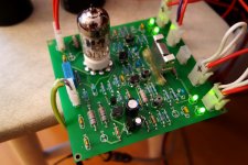
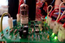
Prototyped and tested!
Hi All, here we go.
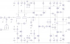
Soldered and measured. Minimal fine-tuning - R2, R6, R7, R9 are adjusted - see attached schematic.
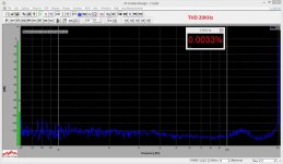
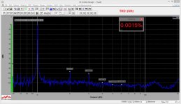
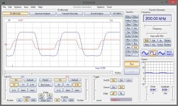
It confirmed its pretty high-end performance. Low noise, low THD, low IMD, high slew rate (400nS rise/fall time), good phase response. Bandwidth with all the compensation and input filter is around 300kHz.
I've tried 2 tubes. First one had pretty high tolerance between the triodes - DC offset at the output was around 180mV. The second tube is matched much better, so offset slowly fluctuates around zero, +/-10mV maximum.
In a worst case it is possible to put a trim pot (470 ohm) instead of R5, R8 degeneration resistors, connecting its central pin to collector of Q3 - it will allow adjusting the offset.
I had no chance to assess the sonic performance yet - need some more time for preparation. However - Terry, Thimios, Ranchu32, jerluwoo and everybody else who is going to build it - you can go ahead and order the PCBs.
Regarding the start-up behavior - the tube warms-up in about 10 seconds. So, you've got 2 options:
1) Setup the soft-start circuit in a way that it gives the power to the heater right away, in 10-12 seconds it powers-up all the rest of an amplifier and after another 2-3 seconds it connects the speakers;
2) Power goes everywhere at the same time, just connect the speakers in about 12-15 seconds.
First option is more "friendly" for the circuit.
I use a small heatsink for Q15, Q17 - even at 4.5 mA they get warm, so heatsink is recommended for better stability.
Questions, suggestions are welcome.
Looking forward to hearing it
Cheers,
Valery
P.S. - I have an idea to try powering the heater with 6V DC (regulated) - it may potentially decrease the risk of influencing the input (though it seems to be unnoticeable even as is, with AC power).
Hi All, here we go.
Soldered and measured. Minimal fine-tuning - R2, R6, R7, R9 are adjusted - see attached schematic.
It confirmed its pretty high-end performance. Low noise, low THD, low IMD, high slew rate (400nS rise/fall time), good phase response. Bandwidth with all the compensation and input filter is around 300kHz.
I've tried 2 tubes. First one had pretty high tolerance between the triodes - DC offset at the output was around 180mV. The second tube is matched much better, so offset slowly fluctuates around zero, +/-10mV maximum.
In a worst case it is possible to put a trim pot (470 ohm) instead of R5, R8 degeneration resistors, connecting its central pin to collector of Q3 - it will allow adjusting the offset.
I had no chance to assess the sonic performance yet - need some more time for preparation. However - Terry, Thimios, Ranchu32, jerluwoo and everybody else who is going to build it - you can go ahead and order the PCBs.
Regarding the start-up behavior - the tube warms-up in about 10 seconds. So, you've got 2 options:
1) Setup the soft-start circuit in a way that it gives the power to the heater right away, in 10-12 seconds it powers-up all the rest of an amplifier and after another 2-3 seconds it connects the speakers;
2) Power goes everywhere at the same time, just connect the speakers in about 12-15 seconds.
First option is more "friendly" for the circuit.
I use a small heatsink for Q15, Q17 - even at 4.5 mA they get warm, so heatsink is recommended for better stability.
Questions, suggestions are welcome.
Looking forward to hearing it
Cheers,
Valery
P.S. - I have an idea to try powering the heater with 6V DC (regulated) - it may potentially decrease the risk of influencing the input (though it seems to be unnoticeable even as is, with AC power).
Attachments
-
 DSC03216.JPG280.9 KB · Views: 275
 -
 @Tube-THD-20k.JPG258.5 KB · Views: 144
 -
 @Tube-THD-01k.JPG261.4 KB · Views: 164
 -
 @Tube-SQR-200k.JPG144.6 KB · Views: 156
 -
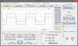 @Tube-SQR-020k.JPG143.5 KB · Views: 505
 -
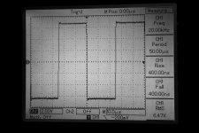 @Tube-SQR1-020k-Rise.JPG328.6 KB · Views: 527
 -
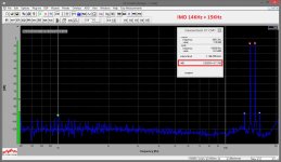 @Tube-IMD-14k-15k.JPG273.2 KB · Views: 553
 -
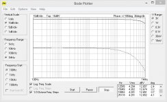 @Tube-Bode-01.JPG70.8 KB · Views: 664
 -
 @Tube-!Sch-02.jpg284.8 KB · Views: 705
 -
 DSC03222.JPG241 KB · Views: 293
Member
Joined 2009
Paid Member

Thank you all for positive feedback, giving even more courage for the future
This is my first serious design with a tube, however I really like the way it performs, so I am definitely going to explore it further. The concept is proved, now it't time to dig deeper
As discussed with Bigun earlier, will try to increase the anode voltage, expecting even better linearity (already ordered a small transformer producing both 6V and 240V AC). Also thinking about using the valve in the second LTP as well...
We'll see
maybe this concept?
http://www.tubecad.com/2010/12/29/PS-6 Simple Schematic.png
... but I am afraid that after rising anode voltage you will be forced to leave dc coupled design concept...
...will try to increase the anode voltage, expecting even better linearity
http://www.tubecad.com/2010/12/29/PS-6 Simple Schematic.png
... but I am afraid that after rising anode voltage you will be forced to leave dc coupled design concept...
Last edited:
http://www.tubecad.com/2010/12/29/PS-6 Simple Schematic.png
... but I am afraid that after rising anode voltage you will be forced to leave dc coupled design concept...
Aha... multiplier... cool, thank you.
I'm going to try keeping the anodes as close to the "main" rails as possible, or even higher, but shifting the level down, before I possibly move away from to coupling
- Status
- This old topic is closed. If you want to reopen this topic, contact a moderator using the "Report Post" button.
- Home
- Amplifiers
- Solid State
- Low TIM, low distortion hybrid front-end