Sorry i haven't any progress yet, my P.C.U is only +/-50V.OK. Finished soldering SlewMonster. Got 3 output pairs so far - more transistors to come in a couple of weeks.
Connected everything, switched on, set the bias, and... no problem
No stability issues. 20KHz square wave response is perfect, no sign of ringing. Excellent sound - same great bass, natural mids, airy highs...
SlewMonster is a great power section - it does not actually influence neither frequency, nor phase response, at least within 1MHz (as far as I can see on my analyzer). I use 33 pF caps at pre-drivers and do not use optional 68 pF caps at the drivers.
Terry, let's think what can be different in your setup. Power supply? Wiring? Tubes? Are you sure you connect PD+ and ND- wires correctly? I mean, at my front-end they are "mirrored" relatively to SlewMonster - PD+, being "at the top" on front-end PCB, is placed "at the bottom" on SlewMonster. Another thought - grounding. I have G1 and G2 directly connected with a wire at my prototype. Is it the same at yours?
I experimented with increasing LTP degeneration and adding the grid stoppers (cutting the traces and soldering them right on top of the gap). Also increase the VAS cascode load (decreased R26, R27), slightly decreasing VAS gain and ensuring less dependency on the power section input impedance.
Those changes potentially further improve stability, but there was no problem without them as well. I've tried to run very fast single impulses with high amplitude, fast-front square waves - I've tried everything. Solid performance. Attached schematic is the one I have on a test bench at the moment.
Thimios, did you progress with building your copy of the head-end? It would be interesting to have more "statistics".
Cheers,
Valery

Maybe you could mark up a schematic with VR and VBE readings so I could have something to compare to. I had hoped that maybe I had the PD, VD reversed. You used all red wires and it is too hard to try to follow them but I just got home and rechecked and the PD is definitely closest to the V+ and ND is closet to the V- so I had it hooked up correctly. Weird thing is that it works fine if I tie the NFB from the IPS to it'self but when I try and tie the NFB from the OPS it looses it. I'm doing that again until I can be certain that the IPS is running where it is supposed to. I'll need those readings from you to do that.
Thanks, Terry
Terry, I will mark up my readings just next to yours for easy comparison as soon as I'm back home today.
Adjustable caps may be an issue if the actual values vary from the required ones - compensation "likes" the right values.
Cheers,
Valery
Member
Joined 2009
Paid Member
Terry - do you have a CRO ? ... if you can identify the frequency of oscillation it gives another clue.
In 100's kHz range it is usually feedback via the wiring, e.g. speaker cable to input
In MHz range it is the amplifier internal feedback loop unstable / inadequate compensation and often bias is unstable and zobel resistor gets warm
In 100MHz range it is output devices self-oscillating (MOSFETs) - usually too fast to see on a CRO but not being able to see it and having very hot zobel resistor and hot output devices is a give-away.
Sometimes you can pick up the oscillation on a small radio.
Last edited:
Thanks Valery,
I think that will be useful. I set the caps using my capacitance meter before installing. I've never used adjustable caps before. I see thimios using them all the time and thought I'd try them. As much experimenting as I do they seemed like a good idea. Maybe not. I will replace them this morning if I have all the correct values. BTW, what circuit did you use with the Slewmaster? Your original or one of the more recent modifications?
Thanks, Terry
Thanks Valery,
I think that will be useful. I set the caps using my capacitance meter before installing. I've never used adjustable caps before. I see thimios using them all the time and thought I'd try them. As much experimenting as I do they seemed like a good idea. Maybe not. I will replace them this morning if I have all the correct values. BTW, what circuit did you use with the Slewmaster? Your original or one of the more recent modifications?
Thanks, Terry
Hi Terry, I used the one attached (got it from Jason).
Cheers,
Valery
Attachments
I knew I didn't ask that right. I want to know which version of the "Low TIM Hybrid" circuit you used.
Thanks
Ahhh... sorry, I also did not read it right
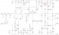
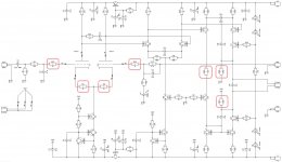
I first tried the "less tuned-up" version (first attachment) and then I tried the latest one, with some additional modifications. Both showed no issues. The second one is the most preferable in terms of both stability and overall performance.
Red boxes indicate what is changed comparing to the previous version.
Please don't pay attention to C4, C12 caps position on the pictures so far - they are in their initial position on my PCB. The way they are illustrated is reserved for future builds (potentially better PSRR).
Attachments
Hmmmm, I made the changes to the board to match the latest schematic and tested it stand alone, and the oscillation is the worst so far so obviously I have something wrong somewhere. Looking forward to the schematic with your readings.
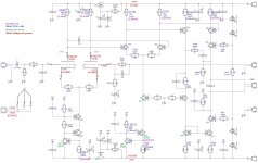
Here is the schematic with not all, but the most important readings.
You've got a very strange reading across R15 (22K) - looks like the meter has lost the contact or something - it can't be zero...
The tube is 12AU7, not 12AX7 by any chance? Well, I'm asking stupid questions as it is very strange it's oscillating... something is really wrong, we need to find out what it is
Power supply voltages coming from OPS are lower than expected in my setup (they were ok with my OPS, but pretty low with SlewMonster - I will check why cap multipliers take more voltage than expected. But this is not really important - the front-end is operational even with the the lower rails.
I continue thinking, what could be the cause...
Attachments
OK, found my mistake, causing my front-end rails being so low with SlewMonster.
Really stupid mistake. Q101 and Q102 (NPN and PNP) were exchanged with each other.
Nothing is damaged though - just exchanged them back to the right positions and now they give +/- 69.1V to each rail accordingly.
But it still does not solve your oscillation problem, Terry. The readings now came very close to yours.
BTW, since it oscillates even without the OPS, you can measure the the oscillation frequency relatively safely with oscilloscope (as Gareth suggested earlier). Can you?
Member
Joined 2009
Paid Member
I switched tubes and now it looks clean on the IPS. Had to leave so didn't get to try it through the ops yet.
OK. Try it with some powerful resistors between the power supply and OPS rails (like 20-50 Ohm 10-20W or something like this). And if there is a sign of oscillation - just switch it off right away. Through-current is what killing the outputs during high-frequency oscillation (when both NPN and PNP are open at the same time). Resistors will limit the current to acceptable level for some time...
I will also try to switch tubes tomorrow (got 8 of them including the one I'm using now). Let's see if it will lead to some changes except some possible DC offset difference.
Last edited:
I suggested that back in post #199
It's have 4 tubes and have been swapping them in and out throughout testing. Sorry if I didn't acknowledge your suggestion.
Last edited:
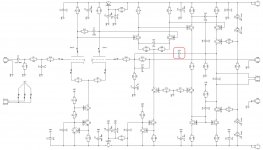
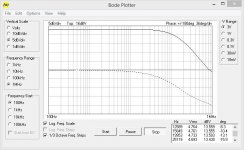
Just tested even more aggressive way to add stability margin. 15pF capacitor, marked by red square, adds a nested loop at HF, limiting the bandwidth and increasing the phase margin (see Bode plot), leaving no space for oscillation. A slight drawback is an over-compensated square wave response, but this is fine in the circumstances we've got. Let's try it this way (first the front-end alone, then, if everything's fine, carefully with OPS).
Attachments
Hi Valery,
Success! It is working. I will try adding the cap you just added as well but it works. Not the best looking 100khz square wave but looks nice at 20khz. I have a 1.u cap in C1 because that's all I had but I have the 2.2u now so I will switch it out before I try playing music through it but no more rejection by the OPS. I'm pretty stoked. Going to mod the other board now to match this one.
Thanks for all your help.
Blessings, Terry
Member
Joined 2009
Paid Member
This will be my first build using tubes of any sort. I just ordered two each off the lesser expensive end of the scale, I hope these will suit the purpose (I did request matched sections):
Electro-Harmonix 12AU7A / ECC82EH Additional Options: Matched Triodes (Balanced)
Tung-Sol 12AU7W / 6189 Additional Options: Matched Triodes (Balanced)
EDIT: Forgot to ask - Valery, which of the schematics would you recommend? There have been a few tweaks and mods and I'm not even sure which one Terry had success with in the end...
Last edited:
- Status
- This old topic is closed. If you want to reopen this topic, contact a moderator using the "Report Post" button.
- Home
- Amplifiers
- Solid State
- Low TIM, low distortion hybrid front-end