My biggest issue is how to model 3 full range drivers in parallel with the woofer.
"Three" is a bad number unless your amp can handle them in parallel. Four can be wired series-parallel. Since your speakers are playing only north of their resonance, your situation is more benign than most systems face.
Are you making a 360-deg speaker with the drivers 120-deg apart? Doesn't sound promising except for an airport waiting room.
Bi-amping solves many problems. Working with a mic and testing is the right way to go, esp if you buy a variable active crossover and just dial-in the optimal test settings.
B.
I realize three is a bad number due to having to choose either parallel or series hookup configuration on the full range drivers. My solution to this problem was to wire them in series.... this means that each full range driver receives 1/3rd the power that it would have originally (Versus if there was only 1 full range driver).
However, this should be fine. We know that at 1/2 power a speaker experiences a 3dB drop in the frequency response. 1/3rd power equates to a 4.77dB drop in the frequency response (For each driver). I did attempt to wire them in parallel, but this would mean there combined impedance in the midrange would dip down as low as 1.5Ohms. This is much too low, so if I wanted to stick with three drivers the series configuration is the most practical approach.
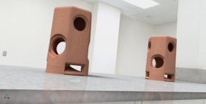
When modeling with a single PS95 full range driver, I had to attach an L-PAD to bring it down to the level that the W5-2053 was putting out. Due to the omnidirectional behavior of low frequencies versus the directivity experienced at higher frequencies... the W5-2053's frequency response relative to the listener should remain similar regardless of its orientation (Because of the cone it downfires into). I've crossed it over to the PS95 at approximately 800Hz, so there might be a dip from 500Hz to 800Hz where directivity matters 'more'. The idea behind these speakers is that they can be mounted 20 feet apart from one another in a large room.
Last edited:
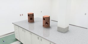
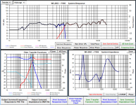
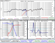
Attached are some screenshots. Top level is Full Range. Second Level are Passive Radiators. The first crossover picture is mine, I multiplied the ZMA file impedance by 3 and decreased the frequency response on the FRD file by 4.77 to reflect the decrease in power. The second crossover picture is the Microfarad Build V2. Let me know if you see any obvious issues with the design. Im relatively new to all of this... I built a pair of Jon Marsh Modula bookshelf speakers in college. I also repaired a pair of HB1 Heybrooks. The cabinet is complex... but it will be built to exact specifications, that I promise. For the renders they are much too close together then they will be when listening.
Attachments
Last edited:
For some reason I am unable to edit my post. So the stereo option of these speakers is second to the mono capability (I dont plan on using them together unless the room is really huge). Ideally only one will be driven in any situation where a room is trying to be filled with sound. For the mono amplifier I plan on using a Sure Electronics AA-AB31282 1x200W Class D Audio Amplifier Board - T-Amp. I'm still looking for a pre-amplifier however (I cant seem to find a simple small mono amplifier... other than the 100W Nobsound amplifier that seems kinda cheap / unreliable - the non-subwoofer version).
The biggest concern of mine at the moment is the impedance plot on the left crossover plot. That spike up to 24 ohms... will that be an issue for the amplifier? To my understanding only low loads are difficult on the amps, but surely there must be a reason against an impedance that is too high, no?
The biggest concern of mine at the moment is the impedance plot on the left crossover plot. That spike up to 24 ohms... will that be an issue for the amplifier? To my understanding only low loads are difficult on the amps, but surely there must be a reason against an impedance that is too high, no?
Class D amps have an LC output filter usually set to give a Q of 0.7 with a 6 ohm load. If the load has a higher impedance, the Q changes and creates an unnatural boost in the upper treble. If that's the case with the Sure amp working with your speaker, perhaps you can mitigate it with a zobel filter in parallel with your series of 3 full range drivers?
Its an interesting project but not how I would use small speakers and an inefficient sub to fill a large room. I'd try to exploit the room corners to work as horns and get a very efficient sub. It'll be interesting to see what kind of spl you get from this. I guess volume is not a concern?
Its an interesting project but not how I would use small speakers and an inefficient sub to fill a large room. I'd try to exploit the room corners to work as horns and get a very efficient sub. It'll be interesting to see what kind of spl you get from this. I guess volume is not a concern?
Last edited:
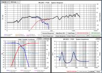
So I decided to convert the 3 Full Range drivers back to a parallel arrangement and was able to get to this response. The impedance plot looks MUCH better than what I had before. The phase stays within +/- 30 so I would say this looks good... would you agree?
So I'm trying to build this speaker as small as possible. I guess I thought it would be cool to have for small parties or get-togethers.
So I'm trying to build this speaker as small as possible. I guess I thought it would be cool to have for small parties or get-togethers.
I'm going to mess around with some different techniques and see if I can reduce the woofers resonant frequency impedance rise. If for some reason I'm unable to get that below 25 Ohms.... would you say an efficiency mismatch is better than having the full range drivers slope upward above 30 Ohms? I realize these questions usually aren't frequent with standard 2-way, 2.5-way, or 3-way designs... the full range driver arrangement is definitely throwing a wrench in the process (Which is probably why its never done), however! I am determined.
And slightly stubborn
And slightly stubborn
Last edited:
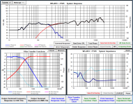
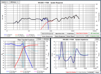
So this may be the crossover I end up going with. It seems balanced from an impedance perspective. Under 25 Ohms for both the Woofer and the Full Range driver. Two peaks at 23 Ohms at both 30Hz and 500-600Hz... Lowest dip is to 5 Ohms at around 110Hz, my biggest concern is how the phase is at 45 degrees at 200Hz since the impedance is at 8Ohmish, so even though its 45 degrees thats a pretty nominal impedance for an amplifier. I think Im going to keep messing around however since the tradeoff for the more balanced impedance curve is a sloppier crossover... the below image is of a series hookup configuration.
For anyone looking to model in series... make sure to modify you FRD and ZMA file... for instance, I put 3 Full Range drivers in series, so subtract 4.77dB (1/3rd Power) from every frequency SPL point in the FRD file and multiple the impedance points by a factor of 3. Then work with it in a crossover modeler.
For anyone looking to model in series... make sure to modify you FRD and ZMA file... for instance, I put 3 Full Range drivers in series, so subtract 4.77dB (1/3rd Power) from every frequency SPL point in the FRD file and multiple the impedance points by a factor of 3. Then work with it in a crossover modeler.
Attachments
Last edited:
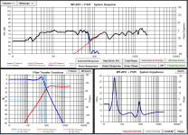
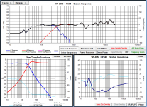
I think I've found a solution that I'm happy with in all respects... Impedance, Phase, Crossover Point. Second order filter on both the Low and High... I ended up having to use 100uF and 5mH inductors to smooth things out. I wonder if this will have an audible effect on the sound??
Attachments
Caps and coils both work as energy storage-release so the bigger they are, the more noticeable their effect, however, for your design, it seems unavoidable and probably of little relative importance. Its one of the reasons both Ben and I tried to nudge you towards having two lower powered amps rather than one bigger one - line level components are more benign, and cheaper too. However, those curves look good and engineering is often about finding suitable compromises.
I spent a while looking for a good line level crossover (That was relatively small and affordable). I was unable to find one. My goal is to drive each one with a single small mono amplifier... I want to keep as many components inside the speaker as possible. The line level crossover would have meant having another external component in addition to the amp, a tradeoff for more flexibility in tweaking the crossover.
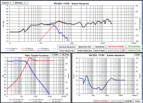
If I decide to go with implementing a passive crossover, I am stuck between the two crossovers below. One has a more reasonable impedance curve (The Left), however the other has a better crossover transition (The Right). What do you think?
If I decide to go with implementing a passive crossover, I am stuck between the two crossovers below. One has a more reasonable impedance curve (The Left), however the other has a better crossover transition (The Right). What do you think?
Attachments
I'm reluctant to choose either but the left looks better. Did you account for any zobel, l-pad, notch filter, etc. I suspect that neither will be very satisfying and will need some trial and error fixes. It can be quite frustrating to get a full range driver to sound right, never mind 3 of them blended with an inefficient sub. If it does work out in practice though, props to you! If I was doing this, I'd be lazy and buy a 5.1 system with 5 identical satellites. I'd get four door hinges and hinge the 5 satellites together as a foldable bank. I'd make a centre column to fit onto the sub and run the 5 satellite speaker cables inside the column. Then I'd only need a signal and power. Job done but not half as much fun eh?
Last edited:
For the crossover on the left (The one that you think is the better choice). The subwoofer crossover is second order. The subwoofer has a 5mH inductor and a 47uF capacitor making up the low pass filter. Then I have a 100uF capacitor in parallel with the subwoofer.
The full range drivers have a second order as well... 47uF and 3.5mH inductor make up the high pass filter and then I have a 25 Ohm resistor in parallel with the array of series linked full range drivers, this basically reduces the load the amplifier sees when the impedance of the full range drivers start to rise... at the expense of them having to dissipate 60Watts if Im maxing out the system. To dissipate that power, Im going to chain 5x 5 Ohm Mills resistors (Rated at 12W) in series. I don't plan on ever hitting this number however.
I think its a fairly simple crossover... we'll see how they sound I suppose. I have high hopes for these, but obviously they're are some glaring shortcomings with this design. Since I started with a repair, and then building a pre-designed design - I figured it was time to try something on the more daring side.
Last edited:
I'm reluctant to choose either but the left looks better. Did you account for any zobel, l-pad, notch filter, etc. I suspect that neither will be very satisfying and will need some trial and error fixes. It can be quite frustrating to get a full range driver to sound right, never mind 3 of them blended with an inefficient sub. If it does work out in practice though, props to you! If I was doing this, I'd be lazy and buy a 5.1 system with 5 identical satellites. I'd get four door hinges and hinge the 5 satellites together as a foldable bank. I'd make a centre column to fit onto the sub and run the 5 satellite speaker cables inside the column. Then I'd only need a signal and power. Job done but not half as much fun eh?
That sounds pretty fantastic actually. However, this speaker is only 14 inches tall though (9 Inches wide). When I initially thought of it, I imagine it going in the center of an apartment... or on a ping-pong table at a party. When I get together with friends we always have a crappy JBL bluetooth speaker in the center of the room. I thought I'd try to create a tower that performs that task better. This design would never work up against a wall. It might work on your desk if there was a switch to disable the two drivers in the back and somehow re-route to a different crossover.
For the crossover on the left (The one that you think is the better choice). The subwoofer crossover is second order. The subwoofer has a 5mH inductor and a 47uF capacitor making up the low pass filter. Then I have a 100uF capacitor in parallel with the subwoofer.
The full range drivers have a second order as well... 47uF and 3.5mH inductor make up the high pass filter and then I have a 25 Ohm resistor in parallel with the array of series linked full range drivers, this basically reduces the load the amplifier sees when the impedance of the full range drivers start to rise... at the expense of them having to dissipate 60Watts if Im maxing out the system. To dissipate that power, Im going to chain 5x 5 Ohm Mills resistors (Rated at 12W) in series. I don't plan on ever hitting this number however.
You mentioned you were using PS95 - Dayton Audio? And 3 in series? They are 7.1R and 0.63mH each (?), so 21.3R and 1.89mH for three. A zobel shunt across all 3 to correct the impedance rise would be 26R and 2.7uF. 25R alone will do it but this is still 21 ohms for the amp at high frequencies, an it is designed for 8 at the highest. This will result in a rising output above about 6kHz, +0.5dB at 10kHz, +2dB at 20kHz, and peaking at +3.8dB at 35kHz before the cliff roll off. So although the graphs look good, it seems that perhaps won't be what you hear. And that's assuming the amp is designed for 8 - if 4 then the peaking will be more.
What's the purpose of a second capacitor across the sub? It seems you have a 5mH and 147uF second order on the sub? Something else?
With 3 PS95 in parallel, you get 2.4R and too much efficiency so you can add 1.5R to 5.5R in series to sort out the low impedance, and then L-pad the 4R or 8R speaker to get it to match the woofer spl. It also makes the second order filter easier to design for a consistent 4R or 8R or whatever you choose. I would think parallel is a better choice?
I'm currently re-doing a 2.1 amp for rear surround speakers, and I'm using this below for the 50W sub amp with a similarly priced 24V 5A smps supply. I'm gonna try a TK2050 t-amp for the satellites (that have a roll off below 120Hz) and I'll change the input capacitors on the TK2050 amp to 0.047uF to create a high pass with the amp's 20K input impedance. This will give both sub and full range drivers a second order crossover around 120Hz, with some adjustment of both volume and frequency possible on the sub. I might shift that higher with even smaller input caps to reduce the bass load on the satellites - the caps are cheap and it's easy to do.
??? ??????12-24V?????? TPA3116??????-???
Last edited:
Im getting ready for work for I'll have to be kinda quick here. I can investigate more tonight however. So I modeled the crossover with a 26Ohm and 2.7uF capacitor in parallel to the full range driver array and got an impedance curve much higher than the 25Ohms alone... I think maybe the modeler is not 100% accurate to some level?? Picture attached below.
The 100uF capacitor is attached across the terminals of the sub (In parallel) so its acting more like a zobel to attenuate the impedance spike at the woofers resonance rather than summing with the 47uF to modify the crossover point. Hope that makes sense, I will check out that amp.
Not sure how overprice these are... but I think i found a line level crossover that appears to be simple and of decent quality: K231 Stereo 3-Way Active Crossover – Xkitz Electronics
Attachments
You could try this as a model - a linkwitz riley crossover for two 4ohm drivers at 250Hz uses 5mH and 80uF in both low pass and high pass configurations.
The sub most likely doesn't need any other components but you could use a zobel shunt on it of 4.5R and 10uF to keep the impedance constant.
The triple driver wired in parallel could have a 1.5R series resistor on its input to make it appear as 4 ohm load, and reducing output 2dB (measured in watts, 4dB in volts). It can be further attenuated with an L-pad before the series resistor, although I don't know what values to use cos I can't work out dispersion and SPL for a 360deg sound field. Does anyone know?
For argument's sake, lets say you need to lose another 3dB in the L-pad, so then its values would be 1.2R series and 9.7R shunt. This will keep the nominal impedance at 4ohms for the crossover, fitted before the L-pad and series resistor. Given the T pad design of three resistors, and the drivers wired in parallel, impedance rise should be mitigated. However, if you wanted to ensure it doesn't rise, then a zobel shunt of 3R and 22uF on the triple driver array would do it.
So, to pinch the diagram from wikipedia, R3 is 1.5R, R2 9.7R, and R1 is 1.2R. The triple drivers in parallel (with zobel) are after R3, the high pass crossover is before R1.

That creates a speaker with a nominal 4 ohm impedance for the amp. This would be my starting point for a model.
I don't understand the 100uF idea - that appears to short the amp at high frequencies. Magic smoke time?
The sub most likely doesn't need any other components but you could use a zobel shunt on it of 4.5R and 10uF to keep the impedance constant.
The triple driver wired in parallel could have a 1.5R series resistor on its input to make it appear as 4 ohm load, and reducing output 2dB (measured in watts, 4dB in volts). It can be further attenuated with an L-pad before the series resistor, although I don't know what values to use cos I can't work out dispersion and SPL for a 360deg sound field. Does anyone know?
For argument's sake, lets say you need to lose another 3dB in the L-pad, so then its values would be 1.2R series and 9.7R shunt. This will keep the nominal impedance at 4ohms for the crossover, fitted before the L-pad and series resistor. Given the T pad design of three resistors, and the drivers wired in parallel, impedance rise should be mitigated. However, if you wanted to ensure it doesn't rise, then a zobel shunt of 3R and 22uF on the triple driver array would do it.
So, to pinch the diagram from wikipedia, R3 is 1.5R, R2 9.7R, and R1 is 1.2R. The triple drivers in parallel (with zobel) are after R3, the high pass crossover is before R1.
That creates a speaker with a nominal 4 ohm impedance for the amp. This would be my starting point for a model.
I don't understand the 100uF idea - that appears to short the amp at high frequencies. Magic smoke time?
Last edited:
- Status
- Not open for further replies.
- Home
- Loudspeakers
- Subwoofers
- Low THD Tang Band RBM drivers?