ifrythings said:
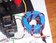
djQUAN, I just made a test circuit and transformer the way it is in ThSpeakerDude88 picture and the mosfets heat up badly and the waveform looks like it got ran over a few dozen times.
The setup
The waveform (See how there in phase, there not suposed to be)
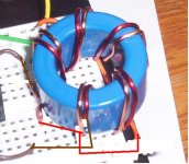
And when I used a different core (with the other winding way that Me and Perry are talking about I get this)
Pic of the setup
And for the waveform: (these ones are out of phase)
P.S the scope is set to the same setting for both test but some reason test #1 dropped in freq.
I was talking about the picture you posted which is the one that should work.
I said I had to disagree because I thought that perry was saying your winding technique won't work. it was ThSpeakerDude88's winding that he was talking about.
yes I figured It had to be the transformer after last nights testing. What I did was since I already had the primary/secondaries wound, I tried it first with both fets ( heat sinked) and the transformer had a high frequency buzz emmiting from it. This lead me to believe " Well the FETS have to be working in phase with each other instead of push pull, that wont work!" I tried running it single ended and the FETS still heated up a bit, but I got 40vdc on the output of one half of the secondary. The wierd thing is that no matter which fet or which driver pin from the chip I used, the other half only read 8vdc. When I attached the smoothing capacitors to the circuit, weird things happened. I got 60vdc on the + leg and 30vdc on the negative leg.
 something is wrong with my transformer. I have plenty of magnet wire to work with and with the small number of turns needed its not a big deal to rewind. I will try the one in your pic, how many primary winds would you sugguest? BTW I changed the frequency to 40khz and ran pin 1 to ground to get the fets to stop heating up. ( as bad, they still heat up a bit on the heat sinks)
something is wrong with my transformer. I have plenty of magnet wire to work with and with the small number of turns needed its not a big deal to rewind. I will try the one in your pic, how many primary winds would you sugguest? BTW I changed the frequency to 40khz and ran pin 1 to ground to get the fets to stop heating up. ( as bad, they still heat up a bit on the heat sinks)djQUAN said:
I was talking about the picture you posted which is the one that should work.
I said I had to disagree because I thought that perry was saying your winding technique won't work. it was ThSpeakerDude88's winding that he was talking about.
Opps... My miss understanding, lol silly me.
ThSpeakerDude88
I think 4-0-4 is a good place to start, just remember to wrap each primary all the way around the core and make sure there not in phase and you should be set.
I have it working finally! I have the transformer underwound right now because I think I have about 6 turns on the primary, and 8 on the seconday. I am powering a TDA2050 with it right now and its working great! I reverted back to the original schematic I had with the 30khz frequency. The fets are on sinks but their not getting even warm. My power transformer is getting mildly warm, and I think that might be due to the fact that I have only 22g wire on the secondarys. I will rewind the xfrmr tonight with bigger wire. Its surprisingly noise free as well 
BTW I am not using driver transistors, and I am using the IRFz24's ( one per side). I am direct driving them from the IC, but when I build the power supply I will add the drivers and the higher power fets.
BTW I am not using driver transistors, and I am using the IRFz24's ( one per side). I am direct driving them from the IC, but when I build the power supply I will add the drivers and the higher power fets.

Thanks for your help guys! I have been following Rods site for some time now btw.
I will be sure to post pics! And when I complete a pcb for it I will post that as well.
Now all I need to do is find out what value of resistor I should use to set the feedback? I have seen some schematics that just use a 5k pot between the + output and pin 1 of the IC. But what about the negative output? Does it get regulated at the same time as the + output?
If you want regulation, use a voltage divider to set the voltage on pin 2 to 2.5v. Use two equal value resistors. Anything between 10K and 100K will work. The top of the voltage divider will go to pin 14. The other end of the divider goes to ground. The mid-point of the divider goes to pin 2.
You can use a pot for the voltage divider on pin 1. One end of the resistive element of the pot goes to the +rail. The wiper of the pot goes to pin 1. The other end of the resistive element goes to ground.
Pin 15 needs to be connected to pin 14. Pin 16 needs to be grounded. You can use this error amp for thermal protection if you want to include it later.
Connect a series RC network between pin 3 and pin 2. The resistor can be anything between 10K and 100K. The cap needs to be ~0.1uf but it's not critical. This provides a bit of stability to the regulator.
well I added a 20k pot between the + output and pin 1. I have 25.5v +/- . If I decrease the resistance going to pin 1 the transformer starts ringing and the voltage increases to a maximum of 30 volts. Whats with this? I have not tried to put higher voltage than 12v into the circuit yet to see if the regulation works.
The transformer is "running out of room" to say.
Is your windings pri 4-0-4 sec 6-0-6?
If you want to regulate the suply you need to have more windings on it so it has room to "play" with, if you have thee above ratio you can't go much higher but you can go lower. If you were to put say 8-0-8 on the secondar then you can regulate it down to the voltage you need and the circuit has some room to adjust for low voltage or high current.
I think I have 7-0-7 , because I am getting 22.5 when I unwind one wind from each. With full windings and 12.4v I get 25.5v, which is perfectly acceptable for the LM3886, but for the TDA2050 it is really pushing the envelope as its operating @ max voltage. I am currently designing a pcb the supply. I think I will have the whole TL494 board a seperate plugin circuit to the main board, that way I can change it around without messing up the main power board. Also it leaves me room to throw a different chip and surrounding circuit in such as the 3525 at a later date.
When the transformer rings, the peak voltage is higher and will cause a higher output voltage (especially with a light load or no load).
The ringing can be caused by an inefficient drive circuit, poor coupling between windings and when the core is pushed to its limit (not the case here). Try inserting the transistor and diode in the drive circuit to see if that helps with the ringing.
The ringing can be caused by an inefficient drive circuit, poor coupling between windings and when the core is pushed to its limit (not the case here). Try inserting the transistor and diode in the drive circuit to see if that helps with the ringing.
- Status
- This old topic is closed. If you want to reopen this topic, contact a moderator using the "Report Post" button.
- Home
- General Interest
- Car Audio
- Low Power: TL494 or SG3525?