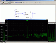
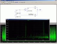
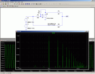
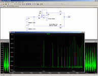
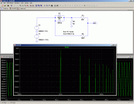
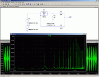
Some hints on oscillators I build, tested and measured with AP-System 2
RC sine oscillator, bulb stab.:
Level
Oscillator with post-filtering:
http://www.ac-vogel.de/AudioMSys/APN 002-Damping oscillator distortion.pdf
Output Buffer:
http://www.ac-vogel.de/TransBuffer_Artikel/TransBuffer_APN_1.html
RC sine oscillator, bulb stab.:
Level
Oscillator with post-filtering:
http://www.ac-vogel.de/AudioMSys/APN 002-Damping oscillator distortion.pdf
Output Buffer:
http://www.ac-vogel.de/TransBuffer_Artikel/TransBuffer_APN_1.html
In general, I tend to agree with you jcx, but not in this case.there's no need for a super low distortion oscillator in audio amp testing - THD is pretty useless by itself
while Cordell's 20KHz THD is a more useful metric than 1KHZ it is less useful than IMD tests which can be done at very high resolution with moderate performance oscillators/signal sources
if you really want to use distortion measurements to improve your amplifier you should want several socillators to look for Intemodulation prodcuts caused by amplifier nonlinearities
I don't think IMD is a better metric of amplifier's quality than THD, rather the opposite.
I will try to illustrate this with a number of cases.
All cases have a normalized THD of 10%, to ease the comparisons.
First is a theoretical ideal 1st order distortion block, with no higher products: see cleanTHD and cleanIM.
Let us compare this with an ideal higher order distortion block: dirtyTHD and dirtyIM.
We see that the IM analysis doesn't bring any more information than the THD, although the signal would sound significantly more unpleasant.
In fact, the THD figure is even a bit more accurate, because it also incorporates higher order products, whereas IM only takes into account the first order product.
Now let's see something more realistic: the equivalent of an underbiased amplifier: Xthd and Ximd.
The difference is striking: according to the IMD analysis, this is an excellent amplifier, when in fact it has 10% of very nasty distortion.
And if the individual values of each harmonic are available, the THD is even more relevant.
Now, I don't say IM figures are worthless, but IMHO, they bring less information than THD.
But if very high resolution measurements of non-linearity can be made only using IM, than it certainly is a useful tool.
Attachments
I own an SG-505 and I like it. It uses NE5534A opamps in Wien bridge arrangement. It produces 0.001% from 10 Hz to 100 kHz and can generate IM test signal. I wonder if it could be upgraded by replacing the opamps to some more modern and lower distortion types?
I tried swapping out the opamps in my Boonton 1120 and it had no effect. Note that in the SG505, the NE5534 have output DC trim and compensation, so rolling opamps may just make things worse. It's only a guess, but I wouldn't put it past the folks at Tektronix to have selected devices for noise.
Your SG-505 should be able to do better than 0.001%, however. Take a look at the signal with a spectrum analyzer or sound card.
I own an SG-505 and I like it. It uses NE5534A opamps in Wien bridge arrangement. It produces 0.001% from 10 Hz to 100 kHz and can generate IM test signal. I wonder if it could be upgraded by replacing the opamps to some more modern and lower distortion types?
I tried swapping out the opamps in my Boonton 1120 and it had no effect.
Well, what jackinnj says is quite reasonable, since the main source of distortion in a SVF ring generator is the peak detector - its residuals, I mean. If I remember well the Boonton uses a track & hold/sample & hold scheme, which is by far the best you can do (it's almost the same topology implemented in AP boxes and in the venerable HP8903). Tek's SG505 peak detector is - more or less - a standard one, so if rolling op amps in Boonton doesn't affect its THD I do not expect you can dramatically improve SG505's residuals by replacing 5534 with, say, LME49710 (which is probably the only one-to-one 5534 replacement with lower THD).
L.
In the last year I've built a couple of prototype SVF generators based on the same concepts - although using an analog multiplier as a level controlling element is somewhat elegant and straightforward, I think it's definitely * not * the best choice if you are seeking for very low THD and THD+N levels (in the 0.001% range or below) - they are simply too noisy (the AD633, which is the low cost analog multiplier I employed in my tests, is noisy, at least). Besides, the circuit shown is imho a little bit baroque in the implementation of the CW freq control and prone to CM thd (as the author himself points out), and the whole ALC loop is somewhat questionable - it's a fixed - and quite small - time constant loop, with proportional gain fixed and probably too high to keep control voltage ripple small. High CV ripple means high THD out even is the SVF topology is an inherently low THD topology (2nd harmonic rejection is not so good unless you manage to achieve very high operating Q, but this needs a very stiff level control loop).
L.
There's also the option of running a square wave into a switched cap low-pass filter. The filter attenuates anything but the harmonic by 80+ dB, so you have better than -80 dB THD...
The switched cap filters are available from Maxim and the square wave can be generated by a micro controller.
Feels kinda like cheating, but it gets the job done.
~Tom
The switched cap filters are available from Maxim and the square wave can be generated by a micro controller.
Feels kinda like cheating, but it gets the job done.
~Tom
There's also the option of running a square wave into a switched cap low-pass filter. The filter attenuates anything but the harmonic by 80+ dB, so you have better than -80 dB THD...
The switched cap filters are available from Maxim and the square wave can be generated by a micro controller.
Feels kinda like cheating, but it gets the job done.
~Tom
Hansen showed that in AudioXpress a few years back -- the pinout of the LT1063 was incorrect in his schematic.
If I recall correctly, the output wasn't quite as stable as one would like.
do you want to test amps or build oscillators?
my point is that “super oscillator” distortion performance isn’t needed so putting designing/building one in the way just slows you down if what you really want is “super resolution” measurement of amplifier nonlinearities
I wouldn't start or stop with a single 2nd order difference measurement - that just illustrates the deep resolution you can get without super low distortion source
you can select 2 tone excitation with frequency ratios that give nth order differences in your filter pass band - a separate test for each order of nonlinearity is a price paid for the high resolution
a 1st pass look with fft at the whole harmonic and IMD spectrum would be a obvious starting point - good soundcards will show any "clearly audible" problem – which also doesn’t require “super oscillator” distortion performance
in general you need n excitation frequencies in complex multitone sweeps to completely map out Volterra kernel n-dimensional surfaces for nonlinearities that fit Volterra-Weiner models - see my "hidden distortion" sim for a circuit with low THD and huge IMD http://www.diyaudio.com/forums/soli...ning-not-whats-your-belief-30.html#post492499
a multichannel DVD player and summing circuits will give very low IMD multitone test source signals - and most of us already own one or more
Last edited:
It surprise me to read so many references to J. Williams (LTC) design
(which AN-43 is based on).
The design, that was the basis of the recent group buy on this forum
(from AN-67) is, actually, based on the idea from John Linsley Hood
design (Wireless World, May 1981. Also, in his book "The Art of Linear
Electronics").
Both adressed the issue of CM distortions reduction, which
supplements the selection of the low dist. opamps to begin with.
Last edited:
Emu 0202 could produce distortion due to ground loop between USB ground and Scope ground. Trying Jensen transformers may help a lot. I use unplugged laptop running from battery for low thdn so ground loop is no more. I enjoyed Emu 0202, 0404 and Tracker for years due to low distortion. Their Line OUT to XLR IN or Headphone OUT to XLR IN connections allowed recording of wave file with THD+N down to 0.0004% I double checked zeroes, no mistake here, EMU 0404. Of course to go that low I had to adjust Line, Headphone out and XLR sensitivity to get exact 0.0004% or in one case 0.00035%. Not on each EMU 0404 unit would go down to 0.00035%. EMU 0202 and Tracker allowed 0.0007% easily.
Peter
Peter
- Status
- This old topic is closed. If you want to reopen this topic, contact a moderator using the "Report Post" button.
- Home
- Design & Build
- Equipment & Tools
- Low distortion oscillator?
