If the controller has proportional action (and it needs this to be fast settling) there is by definition no (significant) low pass filtering. So glitches surely contribute some distortion.
Samuel
Hi Samuel,
Yes of course. I stated that wrong. So what I intend is not by definition proportional.
Cheers,
We are not bound by others' faster settling times. We arent using this on a production line. Longer settling times than the norm are OK. [Not minutes, though.]
-Thx RNMarsh
Well I was thinking more like hours.. No just kiding.
I agree this oscillator is not about fast settling just low distortion.
The settling time of the lamp is not annoying anyway.
100KHz is a bit trying but 10 - 20KHz is a couple of seconds and 1KHz down is less than a second. It might take a second or two more for an leveling circuit to bring it to a reference level. A fast AGC is the wrong thing for this. The lamps are simply to slow responding and cause oscillator squegging.
Another lamp might be just the thing. Does anybody know where I can find a low current miniature dual filament lamp?
One filament for heating and the other.....
Its an automotive taillight. Quite a few choices.
Yes but the current is quite high. 2-3 Ampere.
I need the high heat to isolate from ambient T.
How about a lamp driven LDR assembly?
They aren't made any more but would be easy to fabricate. At low frequencies you will get flicker.
A sample and hold is not really overkill since they can be done with a few integrated parts. The low frequency limits your options. My ac calibrator dumps the s/h for the 100KHz to 1 MHz range but I have not seen an alternative for 20 Hz and below.
A sample and hold is not really overkill since they can be done with a few integrated parts. The low frequency limits your options. My ac calibrator dumps the s/h for the 100KHz to 1 MHz range but I have not seen an alternative for 20 Hz and below.
There is this.
Coupled with a lamp.
This can be connected to a Jfet input op amp.
The setup is the same as what Scott posted for the PV coupler.
Max current of 50uA and a resistor to set the V scale.
I have a 7220 lamps connected to an oscillator running at 10Hz and I don't see any flicker.
I know there is some there but it's not visible to the eye.
The ripple from a lamp is at fundamental. This will pass through an integrator after being compared to a reference.
The integrator will attenuate the ripple further.
This might work.
Attachments
Last edited:
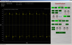
I have the 7220 in series with a 100 ohm resistor.
Input to the series is a 600mVpp square wave.
The QA400 is connected to the vertical output of the scope.
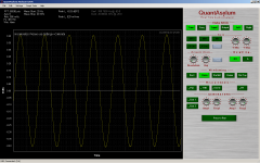
The first shot is the output of the function generator and the second is the voltage across
the 100 ohm resistor in series with the lamp.
I've been trying to measure the tau of the lamp but no luck.
Also with a sine.The waveform is clean on the scope.
The ringing is from the QA400.
Input to the series is a 600mVpp square wave.
The QA400 is connected to the vertical output of the scope.
The first shot is the output of the function generator and the second is the voltage across
the 100 ohm resistor in series with the lamp.
I've been trying to measure the tau of the lamp but no luck.
Also with a sine.The waveform is clean on the scope.
The ringing is from the QA400.
Attachments

I received the PV part and assembled a circuit on some veroboard.
The 339a worked fine. No settling problems so the part is plenty fast enough.
Easy to set up and worked as predicted.
However I could not null the distortion to what I get without it.
Best I could do was about 8dB higher in 2nd H.
So I don't see any advantage with this approach.
But don't through it away it was a non ideal insertion for sure and this may have an influence on the performance.
Cheers,
I received the PV part and assembled a circuit on some veroboard.
The 339a worked fine. No settling problems so the part is plenty fast enough.
Easy to set up and worked as predicted.
However I could not null the distortion to what I get without it.
Best I could do was about 8dB higher in 2nd H.
So I don't see any advantage with this approach.
But don't through it away it was a non ideal insertion for sure and this may have an influence on the performance.
Cheers,
Surprised you can't null the seconds, do you have exactly what you did?
Surprised you can't null the seconds, do you have exactly what you did?
Hi Scott,
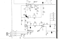
I used the exact circuit you posted.
Instead of using 100k resistors I used a 200k multi turn post wire the same.
A 1 meg resistor parallel the PV and a 1K LED bias resistor.
The whole works connected to the jfet as you indicated. The LED was connected directly to the output of the AGC fet driver op amp and the AGC output was disconnected from the jfet.
Nothing else was changed or different from the original connections.
The only thing missing from this configuration is the coupling capacitor in series with the jfet feedback resistor which adds a bit of filtering.
C30, R51, R50 disconnected and floating. PV LED connected to pin 14 through 1K res.
This may have been the difference.
Attachments
David, are you playing with optocoupler with photovoltaic output and 339a JFET A1Q2 or
with photo FET optocoupler?
http://pewa.panasonic.com/assets/pcsd/catalog/apv-ssop-mosfet-driver-catalog.pdf
http://www.fairchildsemi.com/ds/H1/H11F1M.pdf
Oh, I see... Correct?
with photo FET optocoupler?
http://pewa.panasonic.com/assets/pcsd/catalog/apv-ssop-mosfet-driver-catalog.pdf
http://www.fairchildsemi.com/ds/H1/H11F1M.pdf
Oh, I see... Correct?
Attachments
Last edited:
David, are you playing with optocoupler with photovoltaic output and 339a JFET A1Q2 or
with photo FET optocoupler?
http://pewa.panasonic.com/assets/pcsd/catalog/apv-ssop-mosfet-driver-catalog.pdf
http://www.fairchildsemi.com/ds/H1/H11F1M.pdf
Oh, I see...
Hi Dimitri.
The Panasonic APV1122A.
Those other things are terrible.
photo FETs? slow?
A lot of distortion too for a part that says distortion free in the data sheet.
I was very disappointed.
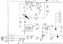
Update on 339a mods
I've done a few more mods to the 339a oscillator and to the balanced modulator board.
I replaced the level pot in the oscillator with a Bourns 10k cermet. This squashed a large 3rd H I just couldn't seem to get rid of. This was a repair.
I replaced the VCR2N with PN4392 Jfet which drove both 2nd and 3rd H down further.
I bypassed the capacitor C30 in series with R51 and added a 100uF electrolytic cap in series with R52. I replace trim pot R30 with a cermet single turn 2K pot.
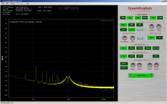
With some tweaking of the amplitude level trim and distortion trim pots got the following results from the oscillator.
The balance modulator board has R5, R6, R32 and R33 changed to 10k. R7, R8, R34 and R35 changed to 1K. I added a balance 10k trim to A3U4 wired same as the balance trim for A3U2. CR1 and CR7 are removed and R10 and R39 are bypassed with a jumper.
A3U1 was replaced with a 1468 in a earlier mod and R1 is set at 200 ohms.
All trim pots are changed to multi turn cermet pots.
This reduced the noise and distortion when setting the balance trims.
The balance trims are set by probing the test points ATP1 and ATP2 with FFT at 1KHz and tweaking the trims for minimal level of signal and harmonics on the the test points.
Here are the results.
I will confirm this measurement once my Twin T is assembled.
Still waiting on some parts.
Cheers,
I've done a few more mods to the 339a oscillator and to the balanced modulator board.
I replaced the level pot in the oscillator with a Bourns 10k cermet. This squashed a large 3rd H I just couldn't seem to get rid of. This was a repair.
I replaced the VCR2N with PN4392 Jfet which drove both 2nd and 3rd H down further.
I bypassed the capacitor C30 in series with R51 and added a 100uF electrolytic cap in series with R52. I replace trim pot R30 with a cermet single turn 2K pot.
With some tweaking of the amplitude level trim and distortion trim pots got the following results from the oscillator.
The balance modulator board has R5, R6, R32 and R33 changed to 10k. R7, R8, R34 and R35 changed to 1K. I added a balance 10k trim to A3U4 wired same as the balance trim for A3U2. CR1 and CR7 are removed and R10 and R39 are bypassed with a jumper.
A3U1 was replaced with a 1468 in a earlier mod and R1 is set at 200 ohms.
All trim pots are changed to multi turn cermet pots.
This reduced the noise and distortion when setting the balance trims.
The balance trims are set by probing the test points ATP1 and ATP2 with FFT at 1KHz and tweaking the trims for minimal level of signal and harmonics on the the test points.
Here are the results.
I will confirm this measurement once my Twin T is assembled.
Still waiting on some parts.
Cheers,
Attachments
Hi Scott,
I used the exact circuit you posted.
Instead of using 100k resistors I used a 200k multi turn post wire the same.
A 1 meg resistor parallel the PV and a 1K LED bias resistor.
Ok, I'll check it out myself, I seem to have a whole week off and nothing but dreary weather ahead. What I want is to check just three or so spot frequencies and I'm happy with fixed oscillators and twin tee filters.
Hi Scott,
I used the exact circuit you posted.
Instead of using 100k resistors I used a 200k multi turn post wire the same.
A 1 meg resistor parallel the PV and a 1K LED bias resistor.
The whole works connected to the jfet as you indicated. The LED was connected directly to the output of the AGC fet driver op amp and the AGC output was disconnected from the jfet.
Nothing else was changed or different from the original connections.
The only thing missing from this configuration is the coupling capacitor in series with the jfet feedback resistor which adds a bit of filtering.
C30, R51, R50 disconnected and floating. PV LED connected to pin 14 through 1K res.
This may have been the difference.
I don't like this very big and nonlinear (PV) resistance at FET's gate. In my opinion, PV must be shunted with capacitor (but this make time constant) and so big pot for trimming not needed - you can change this pot to some kohms without problems.
I don't like this very big and nonlinear (PV) resistance at FET's gate. In my opinion, PV must be shunted with capacitor (but this make time constant) and so big pot for trimming not needed - you can change this pot to some kohms without problems.
Hi Victor,
I changed the resistors to 1K with no change of behavior. The 2nd H was up about 8dB
from norm. How much nonlinear are we taking here, more than a jfet?
Other than that I found them to work quite well.
Cheers,
Hi Victor,
I changed the resistors to 1K with no change of behavior. The 2nd H was up about 8dB
from norm. How much nonlinear are we taking here, more than a jfet?
Other than that I found them to work quite well.
Cheers,
Hi David,
I don't see other reasons for distortions increasing, as circuit at FET's gate. PV also has very big and nonlinear output resistance. I don't know, how big effect it makes - needs calculating or measuring. PV output resistance in series with FET's gate capacitance (also nonlinear).
Maybe you can shunt PV with capacitor (about 1000pF) for experiment...
- Home
- Design & Build
- Equipment & Tools
- Low-distortion Audio-range Oscillator